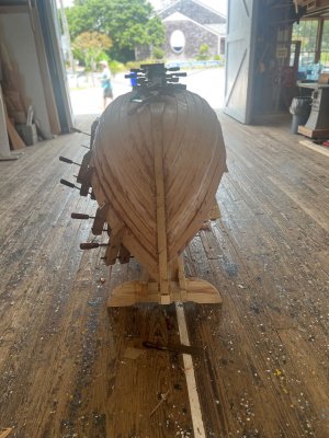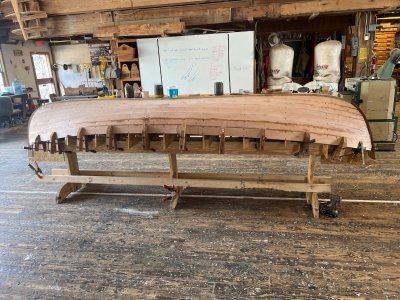


• Ships of Scale has incorportated an extra level of security when you log In. Please follow on-screen prompts to acknowledge that you are not a robot via a "Check Box" or a "Pictorial Check Box Puzzle". This is needed due to higher level of AI Activity Security.
  • SUBSCRIBE TO SHIPS IN SCALE TODAY!

    The beloved Ships in Scale Magazine is back and charting a new course for 2026!
    Discover new skills, new techniques, and new inspirations in every issue.

    NOTE THAT OUR NEXT ISSUE WILL BE July/August 2026
  • Win a Free Custom Engraved Brass Coin!!!
    As a way to introduce our brass coins to the community, we will raffle off a free coin during the month of August. Follow link ABOVE for instructions for entering.

Galway Hooker ‘Truelight’ by Jeff

Joined
Jun 22, 2026
Messages
15
Points
48

This boat is based on the lines of the Truelight which was a 35’ boat. My intention is to develop a solid set of offsets for a 28’ boat by fairing out the lines at 42”. This sets the scale at 1/8th the 28 footer and 1/10th the original. The construction details will be slightly different with fewer frames.

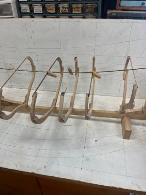
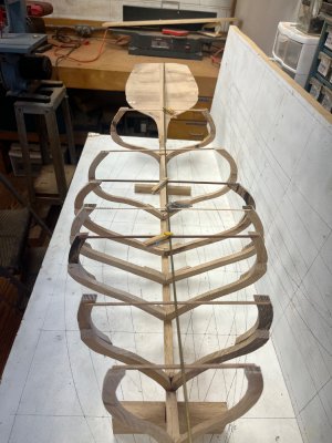
It is lofted out, I have created the backbone timbers, transom, and am working on filling out the 19 full frames. You can see 2,4,7,11, and 15 and I am currently working on 19. Floor Timbers are notched into the knees at either end.


IMG_7418.jpegIMG_7419.jpegIMG_7440.jpegIMG_7490.jpegIMG_7491.jpeg
 
I have added frame 19 here. It is the furthest aft frame with a floor. I have temporarily clipped that rod on the centerline to help keep everything aligned. Not all of the frames are glued in place yet. I will go ahead and document my process for getting out the frames with the next one. You can see most of the ones I have done have been close to the stations which is partially intentional and frame 11 is set on the midship station. I am a boatbuilder so I am just lofting it out in miniature, so there may be an easier way you all know but the new frame drawings will help me improve my table of offsets which is what this is all about.


IMG_7511.jpeg
 
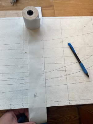
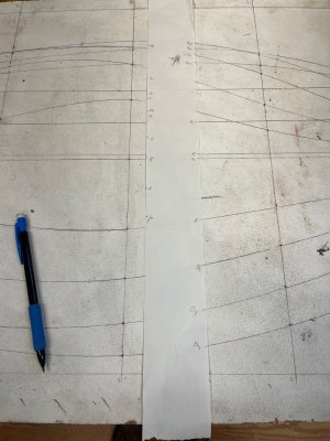
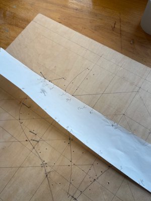
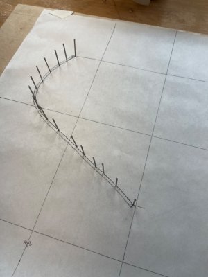
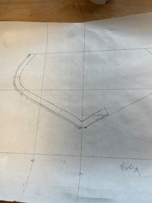
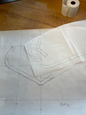
My progress is slow so I thought I might just go through my frame making process. I have already done frame 7 and 11 so I am going to grab 9 right in the middle. I first go to the lofting and determine where the station line will be (face of the frame closest to midships). I then grab the offsets from the profile and half breadth and the diagonals.IMG_7520.jpeg
IMG_7521.jpeg
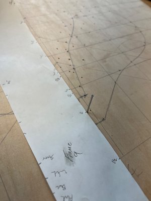
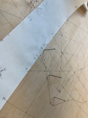
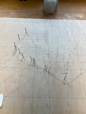
From there I copy them to my body plan board.
IMG_7522.jpegIMG_7523.jpegIMG_7524.jpeg
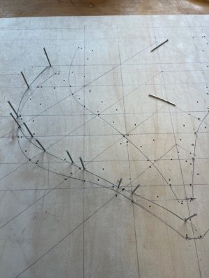
I insert nails at all points giving the shape there (also note bad points that are unfair and should be corrected on the plans)
IMG_7525.jpeg
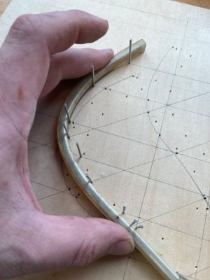
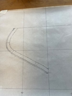
A flexible curve provides a form -IMG_7526.jpeg
IMG_7527.jpeg
These lines are to the outside of the planking so subtract plank thickness-IMG_7528.jpeg
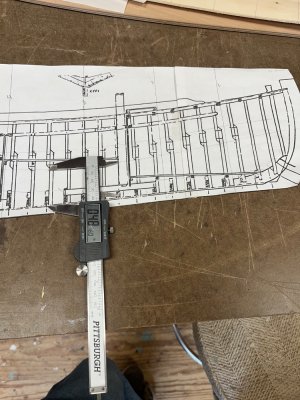
I then grab the heights of the frame component ends from a print of construction details and scale it to my lofting.
IMG_7529.jpeg
IMG_7530.jpeg
Need some guidance across the centerline for alignment.
IMG_7531.jpeg
Finally I can trace the frame parts to make…
IMG_7532.jpeg
Then cut them out
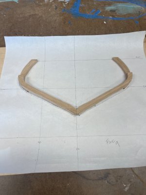
IMG_7565.jpeg
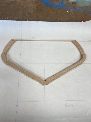
And a temporary connection at the sheer with centerline markedIMG_7566.jpeg
Here is the new frame filling the spaceIMG_7569.jpeg
IMG_7570.jpeg
Hopefully this was useful to someone. About 12 more like this to do.
 
Jeff, nice work as always! To clarify- you are lofting frames that occur between two lines drawing sections. Correct? In my experience, correcting it involves changing other points nearby. In other words, correcting a body plan point as you did also changes nearby waterlines and buttocks. How can you be sure that your frames will result in fair surfaces when you plank the hull?

Roger
You are absolutely right about fairing. You can't just move a single point. After I complete all of these frame drawings I can see where my "problem areas" are and correct all of the points at the same time and create a fair set of lines from them. In the short term for the model, I am relying on the overall hull shapes and sanding it fair to create a fair hull.

From the lines drawings I can create a station line at any point and pull the measurements to create the body plan at that point. I have evenly spaced my frames (I think they are at either 10 or 12" at 1:8 I can't recall off hand). Each frame/floor creates a frame that is 1/2" wide (4" at 1:8). I just need to determine which face (fwd or aft) to use for my frame. Since most boats taper as you move away from midships, I use the face closest to it as the frame shape. This way the outboard face of the frames have "meat" to be faired and let the planks sit flush against the entire face. Fairing from one frame to the next and with (in this example 19) frames to fair from gives a lot of direction in fairing the hull even if an odd point at any one position is off. Will it be a perfect representation of a ship's plan? No, but find any boat built that is!
 
In other words, correcting a body plan point as you did also changes nearby waterlines and buttocks. How can you be sure that your frames will result in fair surfaces when you plank the hull?
The traditional hooker builders knew that fair planking would result from their frames because the shapes of their frames were "lofted in the stocks." Like many primitive watercraft types, hookers were historically never built to "plans" and, at present there are less than a handful of relatively recent sets of lines taken off existing hookers which might yield a table of offsets. As far as I know, the only extant table of offsets for a hooker was developed from lines taken off of Truelight. The modeler here is apparently an experienced boat builder who is building his model working from modern lines and tables of offsets, rather than the traditional building method of "building to the boat."

Hookers ("Huiceiri" in Irish) are a very old vessel type which is traditionally built using patterns for five shapes: the stem, transom a midships section and fore and aft quarter sections. The keel is laid level, the patterns are set up normal to the keel, and ribbands are set up. (The transom pattern may be omitted and the transom shape generated by the battens where varying the rake of the sternpost is desired.) The floors and frames with their distinctive alternating bevel-ended futtocks fastened with three nails and a through-bolt are fitted to the "basket" formed by the ribbands. Carvel planking is hung in the ordinary fashion with the battens and patterns removed as they are encountered during the planking progress. The hooker's distinctive construction details are defined by "rules of proportion" in the traditional fashion. For what it's worth, I suspect think that the traditional construction method is a lot easier than trying to loft frames from a modern table of offsets, once you have the five basic patterns in hand, anyway.

Within certain limits, hooker overall lengths can be modified by expanding or contracting the spacing of the patterns along the length of the keel, or, for greater size differences, the patterns can simply be proportionally enlarged, yielding the four hooker size range classifications, the gaff-rigged bad mor ("big boat,") leathbhád ("half-boat,") and gleoiteog ("cute little boat,") and the lug-rigged pucan ("small cup.") The ribbands ensure the fairness.

Interestingly, while the hooker in its present form first appears in the historical record around the mid-eighteenth century, it was not known how much longer it had existed in its present form until, in 1978, a remarkably well preserved 26-foot txalupa ("chalupa" - whaleboat) was discovered alongside the 1565 wreck of the Basque whaler, San Juan, off Red Bay, Labrador. The medieval Basque whaleboat's construction style mirrored the design principles and details of the Irish hooker and revealed a cross-cultural maritime heritage in the North Atlantic which supports the conclusion that the Irish hooker as we know it has existed relatively unchanged in its present form since at least the mid-sixteen hundreds. This was the boat building equivalent of reeling in a coelacanth for the first time!
 
Last edited:
My first attempt at modeling this boat was actually to go about it in the traditional manner pulling the frame shapes from battens run across three mold frames but I realized it is only easier in full scale where you can get in there and pull the shapes with something like a lead bar. Maybe the modeling community knows a trick for pulling those shapes from a model as it develops from the ground up.
 
You probably know this already but the ribband basket system is usually associated with steam bent ribs. In this case the ribs can be bent and clamped against the ribbands. I don’t know how this technique would work with sawn frames. Cut and try?

Roger,
 
Yes the shape is lifted with something that will hold shape (like a lead bar you can hammer against the ribbands or making a pattern with plywood or cardboard cutting and checking and shaping with a spokeshave. Those builders are good! They can pull the shape, rough cut it with a chainsaw from a full tree width slab and get it into shape with hand tools.
 
My first attempt at modeling this boat was actually to go about it in the traditional manner pulling the frame shapes from battens run across three mold frames but I realized it is only easier in full scale where you can get in there and pull the shapes with something like a lead bar. Maybe the modeling community knows a trick for pulling those shapes from a model as it develops from the ground up.

I do. A number of ways.

1. A miniature lead bar. Seriously. Staedtler drafting tool company actually sells them ready-made. There are lots of other "flexible curve" devices that have been sold over the years.

spons&sp_csd=d2lkZ2V0TmFtZT1zcF9hdGY&psc=1

They're easy to make yourself to serve particular needs, too. I use a strip of plumber's sheet lead backed with a piece of plastic or card stock sufficiently stiff to produce a fair curve, but not so stiff that the lead doesn't prevent any spring-back. The lead strip or draftsman's "flexible curve" can produce a curve mirroring the frame face when pressed against the inside of the ribband "basket." That can be transferred to a piece of cardstock that can thereafter be trimmed as may be necessary to yield a perfect pattern for fitting the frames in place.

2. Use one of the inexpensive plastic locking contour gauges and a irregular curve template. (It's best to use your set of Copenhagen ship's curves. You do have a set, don't you. :D) Otherwise, transfer the points taken up with the contour gauge to a piece of cardstock and draw the curves using French curves or, alternately, spring a batten along the points using drafting ducks or nails to develop the edge against which you can strike an accurate curve. .


3. Copy the shape with a drafting compass. Clamp a wooden or plastic batten in place against the inside of the ribband "basket" along the section line of the frame. Cut a piece of cardstock roughly the shape of the frame curve shape and place it perpendicular to the flat of the clamped batten. Using a drafting compass open as wide as may be necessary, strike a line on the piece of cardstock with the point of the compass running on the flat of the clamped batten. (This is the same technique as when you need to make a pattern to cut a piece of flooring tile to fit an edge.) It is important to keep the compass perpendicular to the chord of the curve.
 
Last edited:
You probably know this already but the ribband basket system is usually associated with steam bent ribs. In this case the ribs can be bent and clamped against the ribbands. I don’t know how this technique would work with sawn frames. Cut and try?

Roger,

Yes, the heat-bent frames approach eliminates the not only the need to develop a shape for sawing out the frames, but it also takes care of beveling the frames, as well. The problem here is that the hooker has a distinctive framing design that's necessary to portray in a model. The floors and futtocks are not "sistered," full-length, but built up in single thickness alternating overlaps of quite beefy frame scantlings. (These boats are built like tanks.) I don't think heat bending those types of frames is going to be practical.
 
I do. A number of ways.

1. A miniature lead bar. Seriously. Staedtler drafting tool company actually sells them ready-made. There are lots of other "flexible curve" devices that have been sold over the years.

spons&sp_csd=d2lkZ2V0TmFtZT1zcF9hdGY&psc=1

They're easy to make yourself to serve particular needs, too. I use a strip of plumber's sheet lead backed with a piece of plastic or card stock sufficiently stiff to produce a fair curve, but not so stiff that the lead doesn't prevent any spring-back. The lead strip or draftsman's "flexible curve" can produce a curve mirroring the frame face when pressed against the inside of the ribband "basket." That can be transferred to a piece of cardstock that can thereafter be trimmed as may be necessary to yield a perfect pattern for fitting the frames in place.

2. Use one of the inexpensive plastic locking contour gauges and a irregular curve template. (It's best to use your set of Copenhagen ship's curves. Otherwise, transfer the points taken up with the contour gauge to a piece of cardstock and spring a batten along the points using drafting ducks or nails to develop the edge against which you can strike an accurate curve. .


3. Copy the shape wiith a drafting compass. Clamp a wooden or plastic batten in place against the inside of the ribband "basket" along the section line of the frame. Cut a piece of cardstock roughly the shape of the frame curve shape and place it perpendicular to the flat of the clamped batten. Using a drafting compass open as wide as may be necessary, strike a line on the piece of cardstock with the point of the compass running on the flat of the clamped batten. (This is the same technique as when you need to make a pattern to cut a piece of flooring tile to fit an edge.) It is important to keep the compass perpendicular to the chord of the curve.
All great ideas. I have used them all on full size boats. Don’t think I could get in there with a contour gauge but maybe if I can make a mini lead bar to suit that might work even on this model to get the raked frames far aft. Thanks!
 
Yes the shape is lifted with something that will hold shape (like a lead bar you can hammer against the ribbands or making a pattern with plywood or cardboard cutting and checking and shaping with a spokeshave. Those builders are good! They can pull the shape, rough cut it with a chainsaw from a full tree width slab and get it into shape with hand tools.

Do you have the small book put out by the Hooker Association that has the CD of the building of the Truelight sistership and the full set of lines, plans, and offsets for that hooker? The CD shows how they cut frames out with a chainsaw. Scary, but very impressive. Richard J. Scott's Galway Hookers book contains the information on how they're built and the scantling and design rules, too. These books are unicorns now. Last I saw, a used copy of Scott's Galway Hookers was going for $501, which is a lot of money for a quarter inch thick seven- by nine-inch paperback!
 
Back
Top