-

Win a Free Custom Engraved Brass Coin!!!
As a way to introduce our brass coins to the community, we will raffle off a free coin during the month of August. Follow link ABOVE for instructions for entering.
You are using an out of date browser. It may not display this or other websites correctly.
You should upgrade or use an alternative browser.
You should upgrade or use an alternative browser.
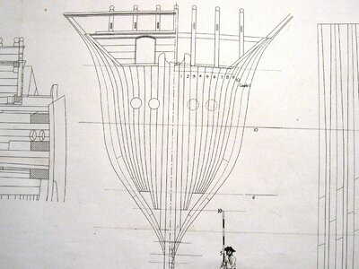
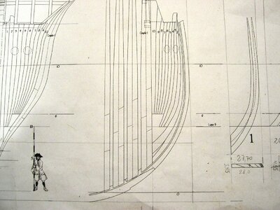
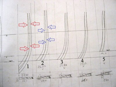
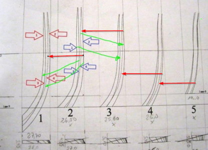
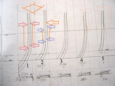
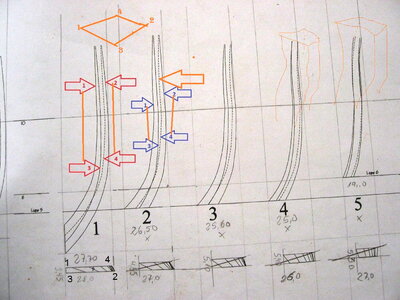
I THOUGHT I understood these drawings. Frank48 has the proper interpretation of the 4 lines, with each numbered drawing being ONE timber, not TWO. Thanks for showing me the correct way to interpret these, Frank48! Making these in wood is a true challenge. You would have to extrapolate a lot of points to a piece of wood on both sides to get the cuts at the correct angles.
Last edited:
- Joined
- Oct 17, 2020
- Messages
- 1,677
- Points
- 488

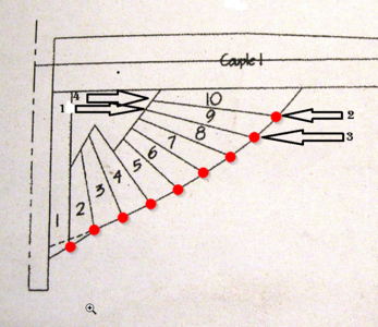
I think I understand these drawings. The solid line are on the outside surface of the hull. Refer to the last picture you posted. The dashed lines are "hidden lines" and are on the inside surface of the hull.
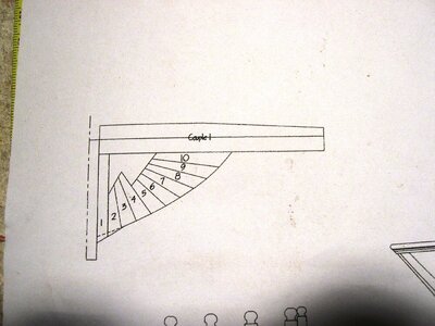
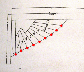
Each drawing with a number (1, 2, 3, etc.) shows two timbers which are joined in a diagonal plane when viewed from the top down. These joints have complex curves, as do the timber themselves. Drawing #1 contains timbers 1 and 2 shown on the hull drawing. Drawing #2 contains timbers 3 and 4, drawing #3 has timber 4 and 5, etc.
You marked the edge lines with numbers 1 through 4. Lines 1, 2 and 3 lay on the outside of the hull, and line 4 lies on the inside surface of the hull. Line 3 is the joint between the timbers on the outside surface, and line 4 is the joint line on the inside surface.
The joints between the timbers themselves are not perpendicular to the outside and inside surfaces of the timbers, but angled. The joint between the two timbers is represented by TWO lines, which you numbered 3 and 4. The plane of the joint changes angle form top to bottom, which is why lines 3 and 4 cross each other.
Once you can understand the three dimensional curves, you can see you the timbers are represented on the drawing. The hard part is taking these drawings and making them into actual wooden parts.
Last edited:
- Joined
- Oct 17, 2020
- Messages
- 1,677
- Points
- 488

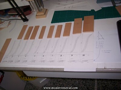
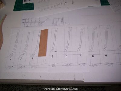
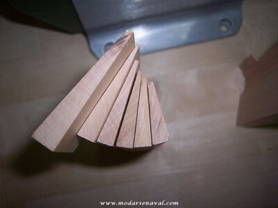
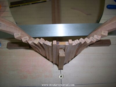
Hello Jeronimo, is this your interpretation?Hello modeling friends,
thank you very much for yours explanations.
The problem is solved with this.
Attached is a drawing from Oliver , (Olivers Historic Shipyard).
Greetings
Karl
View attachment 305087
View attachment 305088
Interpretation von Olivers Historic Shipyard
Karl
Karl
- Joined
- Oct 17, 2020
- Messages
- 1,677
- Points
- 488

Thanks Karl, it's not very clear to me, I'd like to have some more to understand meInterpretation von Olivers Historic Shipyard
Karl
Last edited:
- Joined
- Oct 15, 2017
- Messages
- 1,179
- Points
- 443

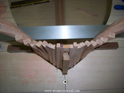
No mistaking the elegant lines of the "front end" and hawse timbers of Le Fleuron. Frank's illustration of a "slice" of a particular timber helps me personally "see" the timber's form clearly. If I were to be building these, I would have to create a data point slice at key intervals vertically up each timber. Karl, I see your construction of the timbers in your photo above and they look very good. I don't recall seeing your build log of Le Fleuron. Have you started yet, or are you progressing with a plan to start it after you are further into the project.
Thanks,
Ken
Thanks,
Ken


