• Ships of Scale has incorportated an extra level of security when you log In. Please follow on-screen prompts to acknowledge that you are not a robot via a "Check Box" or a "Pictorial Check Box Puzzle". This is needed due to higher level of AI Activity Security.
  • SUBSCRIBE TO SHIPS IN SCALE TODAY!

    The beloved Ships in Scale Magazine is back and charting a new course for 2026!
    Discover new skills, new techniques, and new inspirations in every issue.

    NOTE THAT OUR NEXT ISSUE WILL BE July/August 2026
  • Win a Free Custom Engraved Brass Coin!!!
    As a way to introduce our brass coins to the community, we will raffle off a free coin during the month of August. Follow link ABOVE for instructions for entering.

HMS ENTERPRISE by Keith 1:48 scale. New Kit from M.D.

Every thing looking spot on Kieth. Yep my CAF kit also has those gratings and they are quite ridiculous to try and construct. They also are impossible to get the char off so come out dirty.

A quick question - How does your kit (which is impressively accurate) show how the cathead tails finish? Are they bolted to the underside of the deck beams?
Cheers Grant
FWIW on the gratings, i found it quite helpful to get them secured using my small shop vise.
Once located properly you can press them in with fair force using the vise, nothing really twists or snaps, only ones I needed to alter/repair were on the very edges.
 
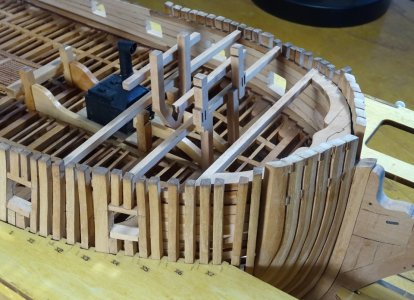
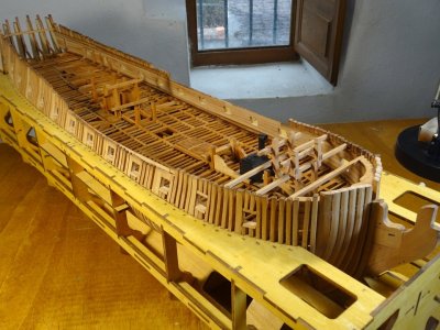
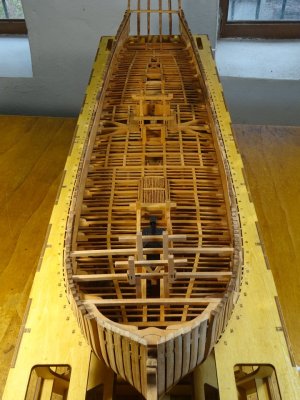
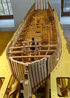
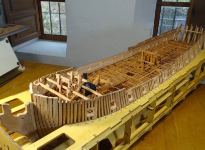
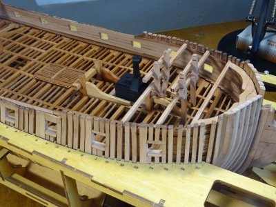
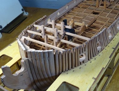
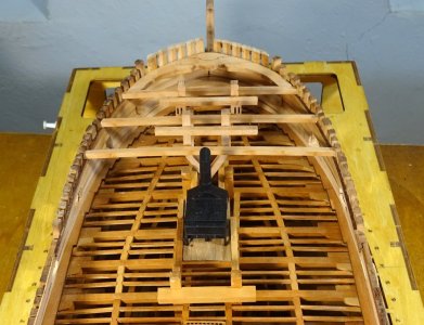
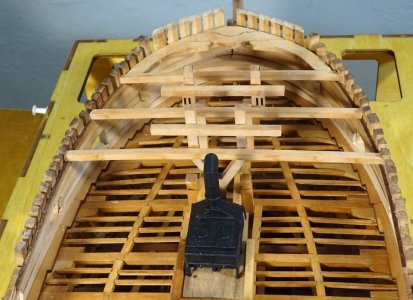
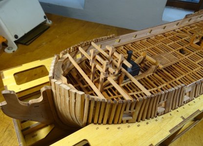
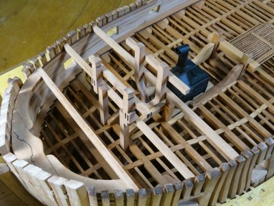
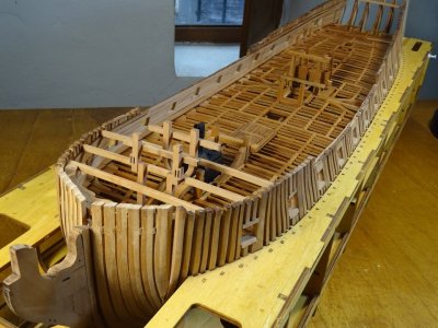
I have actually started with the planking of the inner hull bulwarks and moved on to the foremast bits. Amazingly they fit exactly in position with number 3 and 4 forecastle deck beams. I have also fitted number 1 forecastle beam, but shall not fit any more as yet as the foreward guns have to be fitted under these beams. There are 8 in total and it would be very difficult to the guns with all the beams in position. I have made up and placed the galley stove in its position under the forecastle decking, not including the P.E. parts though, as the very intricate parts are too much for the limited movement of my left hand. I know my limitations

DSC01571.JPG

DSC01572.JPG

DSC01573.JPG

DSC01574.JPG

DSC01575.JPG

DSC01577.JPG

DSC01578.JPG

DSC01588.JPG

DSC01591.JPG

DSC01597.JPG

DSC01601.JPG

DSC01603.JPG
 
Very nice Keith.
If you haven't already don't be in too big a hurry to glue up beams past #1 primarily because while the supplied knees for a couple are done as if they hang down 90deg they need rather extreme angles to avoid obstructing the ports and it takes major fitting for the angles to also fit up with beam sides and flush tops to avoid big gaps with proper spacing.
I found it helpful to make glued sets of beams/knees for fitment, knee and beam side are angled.
This works well....when done, they can be teased into place and then glued without driving yourself nuts trying when beams are already fit.
When all done this way, impossible to discern and all proper spacing for forecastle is maintained.........less frustration.
Example on one....yet to be finish sanded and glued.

IMG_0916.jpeg
 
Last edited:
Very nice Keith.
If you haven't already don't be it too big a hurry to glue up beams past #1 primarily because while the supplied knees for a couple are done as if they hang down 90deg they need rather extreme angles to avoid obstructing the ports and it takes major fitting for the angles to also fit up with beam sides and flush tops to avoid big gaps with proper spacing.
I found it helpful to make glued sets of beams/knees for fitment, knee and beam side are angled.
This works well....when done, they can be teased into place and then glued without driving yourself nuts trying when beams are already fit.
When all done this way, impossible to discern and all proper spacing for forecastle is maintained.........less frustration.
Example on one....yet to be finish sanded and glued.

View attachment 641285
thanks for the headsup on this. will definitely take your advice Thumbs-Up
 
I have actually started with the planking of the inner hull bulwarks and moved on to the foremast bits. Amazingly they fit exactly in position with number 3 and 4 forecastle deck beams. I have also fitted number 1 forecastle beam, but shall not fit any more as yet as the foreward guns have to be fitted under these beams. There are 8 in total and it would be very difficult to the guns with all the beams in position. I have made up and placed the galley stove in its position under the forecastle decking, not including the P.E. parts though, as the very intricate parts are too much for the limited movement of my left hand. I know my limitations

View attachment 641265

View attachment 641266

View attachment 641267

View attachment 641268

View attachment 641269

View attachment 641270

View attachment 641271

View attachment 641272

View attachment 641273

View attachment 641274

View attachment 641275

View attachment 641276
Great work Keith ! Your build looks fantastic !
 
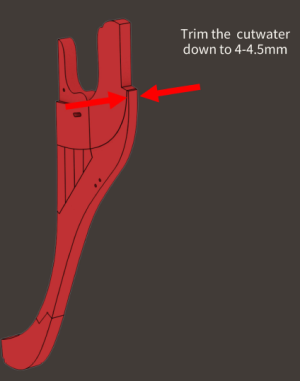
I think MD makes the finest kits available and your build is terrific. I do have a question, hope you don't mind. Do the plans explain that the knee of the head was heavily tapered from 11 inches where it meets the stem to about 4 inches wide at the forward edge and the top of the gammoning knee was rounded or beveled so there were no sharp edges?
Thanks Keef
Allan
 
I think MD makes the finest kits available and your build is terrific. I do have a question, hope you don't mind. Do the plans explain that the knee of the head was heavily tapered from 11 inches where it meets the stem to about 4 inches wide at the forward edge and the top of the gammoning knee was rounded or beveled so there were no sharp edges?
Thanks Keef
Allan
Thanks for your comment Allan. The plan does show a taper although not in such detail. I aim to deal with that at a later time.
 
I think MD makes the finest kits available and your build is terrific. I do have a question, hope you don't mind. Do the plans explain that the knee of the head was heavily tapered from 11 inches where it meets the stem to about 4 inches wide at the forward edge and the top of the gammoning knee was rounded or beveled so there were no sharp edges?
Thanks Keef
Allan
1791217567038.png
Its not as much as you specify. But it does instruct you to taper it. If you tapered it down to a scale 4", it would be just over 2mm wide. :)
 
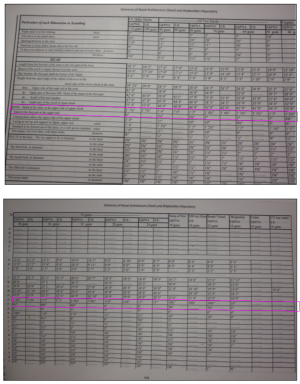
Thanks Keef and Jeff. Yes, it would be thin, but that was the case according to the scantlings in Steel. It had to do with the weight of the head more than aerodynamics.
You can see it was very pronounced for all rates. Neither the Shipbuilder's Repository 1788 nor the Establishments specify the amount of taper, but I did read years ago that in the 17th century and into the18th century the taper was to be at least half the thickness at the fore end compared to the thickness at the stem.

David Antscherl goes into it quite a bit in The Fully Framed Model books as well.
Cheers!

Allan

1791223823342.png
 
Back
Top