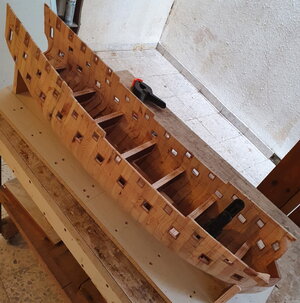
HMS St Albans (1687) model in scale 1:48

Joined
Sep 7, 2020
Messages
27
Points
78

Hello friends!

Ever since i was a kid, i had a dream of building a model of a sailboat so that it is "just like a real one". And I really wanted it to be aesthetically similar to the Admiralty models of the 17th century. It's a pity that such an opportunity was given to me only now, although I have made timid attempts to do something from paper before - for example, trying to imagine what Peregrine Galley would look like before it was converted into a yacht.
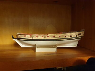
Peregrin_02.jpg

But that's a completely different story.

Building a wooden model was a frightening thing for me: the experience of working with wood was minimal and it was really scary to start the thing. But I really wanted to build something beautiful made of wood,
and even if I can't finish the ship, the process seems to me more important than the result.
By the way, great thanks to the participants of this forum for their work, which i took as an example, and especially to Andrey Kudin for his model building videos on YouTube,
which ultimately influenced my determination to start.

The choice of a prototype did not take much time - there were very few drawings of warships of the 17th century suitable for creating a model, and at the time the construction of the model began I didnt own the excellent book by Richard Endsor - The Master Shiprights Secrets with drawings of HMS Tyger, much more saturated with details, but on this forum
I have found Foxtrott's photos from Trinitiy House, that illuminated the missing details in the St Albans blueprints (for which I am incredibly grateful).

I intended to build the model according to the method of the Mikhail Bezverkhny, where the ship's body is built from halves that are assembled from separate transverse segments.

So - St Albans 1687 in 48th scale!
 
Last edited:
Hi Oleg,
I have a set of plans from Richard Endsor for H.M.S Mordaunt in 1/48 scale. Following this with much interest. :)
 
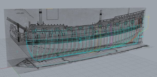
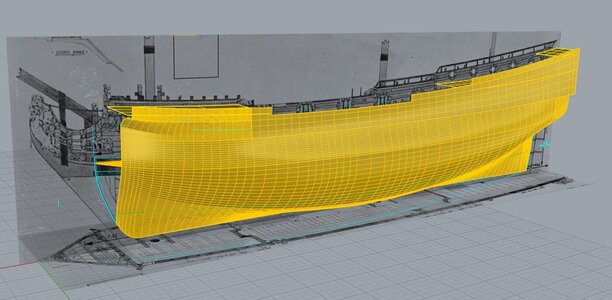
The first thing to do was to draw the frames in Rhinocheros.
I didn't know Rhino too well, so I had to learn everything step by step.

Rhino_1.jpg

The most difficult thing was to understand the shape of the contours in the area of the deadwoods - apparently this is the specificity of the drawing taken from the Admiralty model - it took a long time to verify them, but in the end the result suited me

Rhino_2.jpg

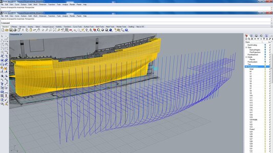
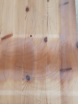
Then the theoretical drawing of the hull had to be re-divided into segments equal to the thickness of the material used - in my case a pine sheet of 22.5 mm

Rhino_03.jpg

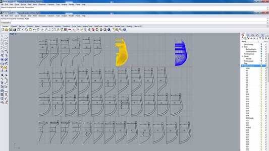
The remaining step was to place the frames separately and print them at the desired scale.

Rino_04.jpg
 
A pine table found on the street was chosen for the construction of the model body, although today I would definitely prefer to use thick plywood for this - too much
problems are caused by the warping of the wood pieces from temperature changes, it was difficult to maintain the same thickness of segments without a thickness planer and it is not known what problems will the resinous knots lead to.

97.jpg

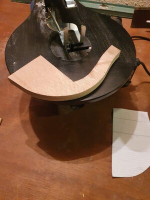
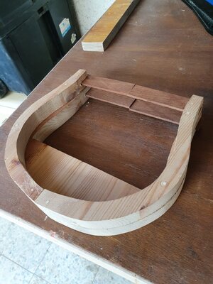
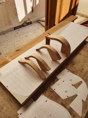
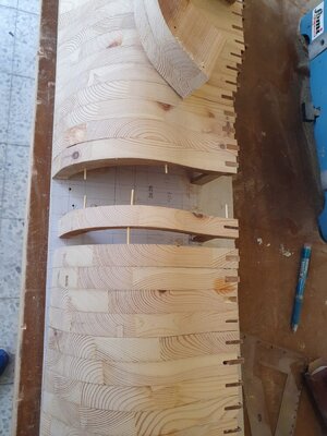
n this image we can see the first frame i have done:

106.jpg

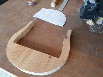
The two halves that form the middle frame:

104.jpg

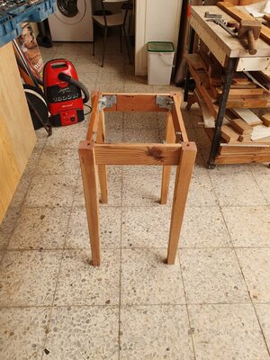
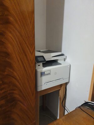
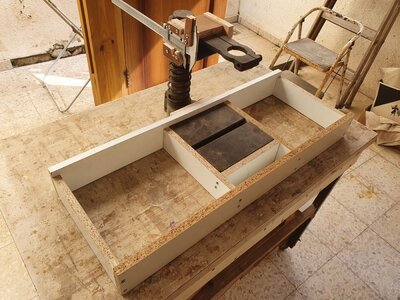
Well, the bottom of the table also did not have to be thrown away - it became a stand for the purchased laser printer

103.jpg
102.jpg

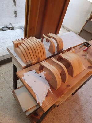
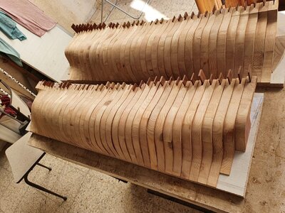
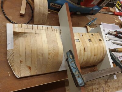
The hull will be assembled from two separate halves on separate boards (for ease of processing). In order to maintain the correct distance to the board, I installed temporary upper parts of the frames.
The frames themselves are temporarily connected to each other with wooden nails (toothpicks) without glue. Every fifth frame is attached to the board with screws.

101.jpg
100.jpg

94.jpg

Finally, the halves are drawn and ready to be processed:
84.jpg
 
It should be a very interesting project to watch. This time, I am taking the first row, sorry Uwe, first come, first serve! :D
 
With the next step I began to shape the hull the with sandpaper. This is how the roughly finished half looks like with the initial markings (to determine the top of the broadside)

111.jpg

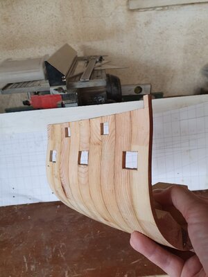
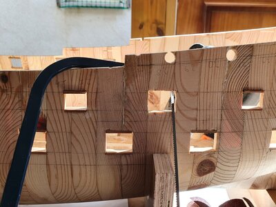
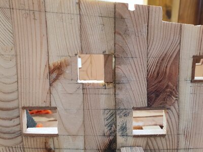
The next step was reducing the thickness from the inside to 5-4 mm, and assembling the halves on the glue. also, I started to cut the ports before gluing the frames, which turned out to be a mistake, and these ports later had to be sealed.

79.jpg
77.jpg
76.jpg
75.jpg


Another small mistake I made, not starting gluing from the inner keel - I had to glue it later. In the meantime, the half looked something like this:

72.jpg
73.jpg

Then I fitted and glued the reinforced inner keel planks

Аrom the experience of the first half, I decided not to cut off the temporary tops of the frames for now
Gluing the second half (the wooden nails are clearly visible):

56.jpg
55.jpg

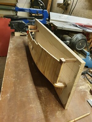
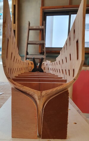
Connected the halves directly on the boards for a couple of days, leveling the body:

50.jpg


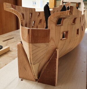
First test build without the boards:

60.jpg
 
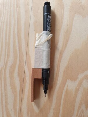
It was necessary to mark the halves of the ship's hull.
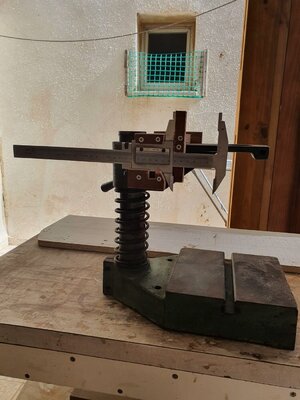
Nothing better came to mind than crossing a calipers with a stand found among my junk
and designed to turn a hand drill into a drilling machine.

This is what the initial version looked like:

40.jpg

In about a day this monster could start to be used: Now the slipboard with half of the hull moved between the guides, and the exposed tip of the caliper was lowered onto the body with the help of the drilling stand handle.

39.jpg

From the marks i got, i could draw the lines of the decks and cannon ports:

33.jpg32.jpg

Inside view with glued-in reinforcement bars:

27.jpg

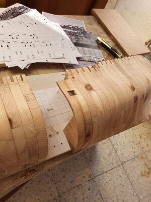
The first cannon port. It was necessary to check how correctly his pearwood frame would sit:

23.jpg

Doesn't look quite bad. can go on:

22.jpg

20.jpg

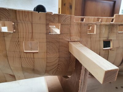
Using bars of the required size, I press down the sides of the port when gluing and later check their parallelism:

5.jpg

11.jpg

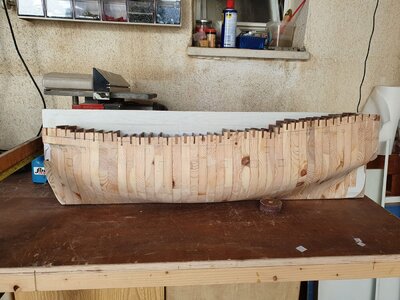
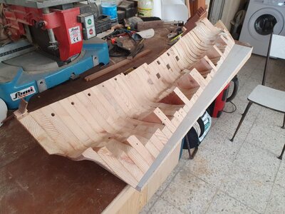
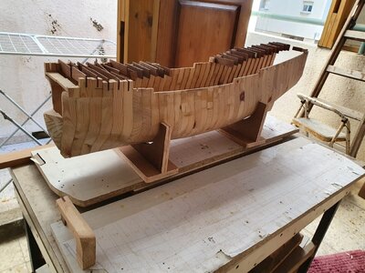
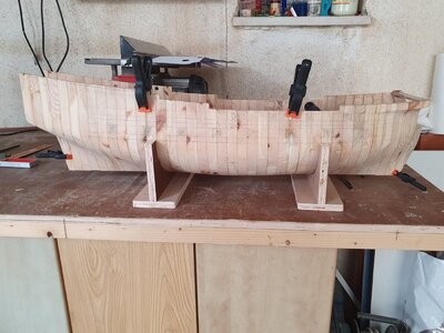
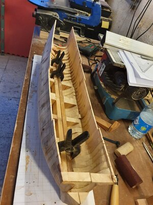
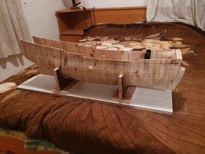
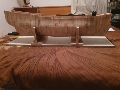
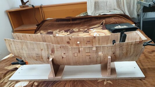
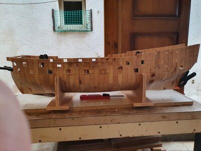
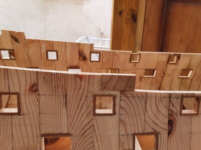
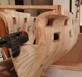
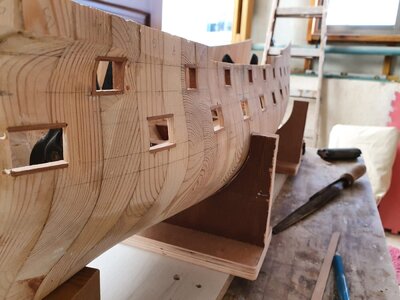
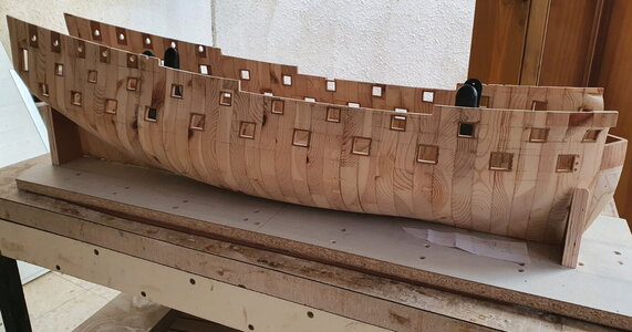
Finally, the last port was cut out today. The ship looks like this:

6.jpg
 
Oh, my favorite theme: 17th century English! Good luck with your construction!
О, моя любимая тема: англичане 17й век! Удачи в постройке!
 
WOW - Very interesting descriptions and photos - this will get a very interesting log of a beautiful vessel

(btw: if you like, you can easily post your photos in full size )
 
Thank you Uwe!
I will use your suggestion for photos.
 
Last edited:
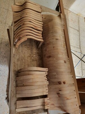
Today's update won't be too big: mistakes maded in the past forced me to come back to fix them.
The main problem remains the lack of longitudinal ties in the hull - in the shortest possible time I have to move on installing the deck longitudinal fastenings and the mainwales, which will immediately strengthen the structure,
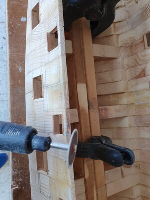
Meanwhile, the temporary solution was pieces of toothpicks glued into the trenches, cut in the places of the weakest joints between frames. Now when I work with sandpaper with effort, they don't try to break up .

144.jpg

There were also several geometric errors. I had to fix it.

130.jpg

135.jpg

134.jpg

But, nevertheless, there is some progress: I have completely finished the frames of the upper cannon ports and the rest are on the way. The next step, the most important and the most nervous one, is
disassembling the hull in half, to remove all excess material in the stern area, mark the inner lines for installing the deck and assemble the hull with glue.

147.jpg

146.jpg137.jpg

btw:

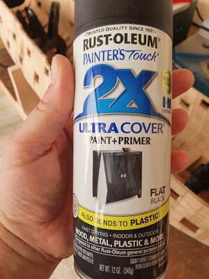
I bought a interesting paint - it contains the primer. Usually I do not like to use sprays - the risk of drips is too high, but I haven’t had to work with wood yet, and I bought paint for experiment.
there is only one drawback - the time of complete drying is 24 hours. Everything else seemed to me a plus

117.jpg

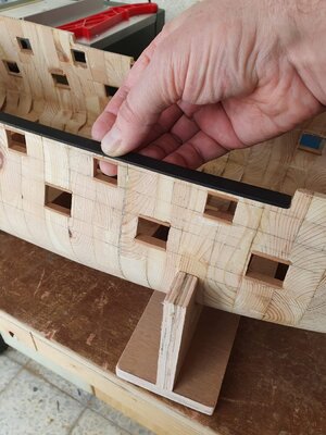
This is how the first layer looked like when tested on a part of the gunwale.

119.jpg

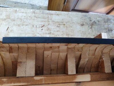
And this is how the final paint coat looked.

136.jpg

All the details of the wood are emphasized (including the saw marks that I was too lazy to grind ) and the semi-gloss is preserved.
I like it.
 

Attachments

  • 145.jpg
    145.jpg
    112.8 KB · Views: 13
Last edited:
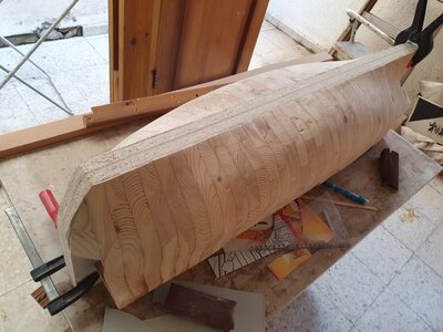
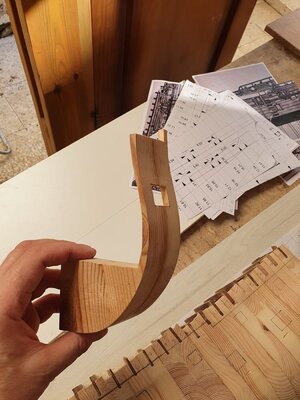
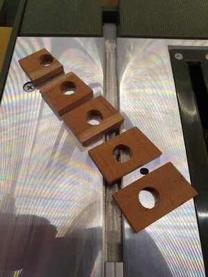
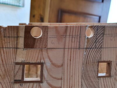
I finished at last with the edging of the cannon ports and began to work with the pearwood inserts for holes drilling - round ports on the quarterdeck and anchor hawses

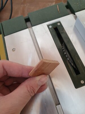
set of inserts for one side

10.jpg

Pasting on the place

8.jpg

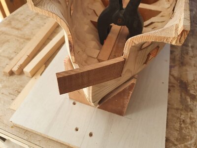
Checking of the nasal insert on the place. The wood already has a slight bend and fits almost perfectly.

30.jpg

cutting

29.jpg

The result

41.jpg

View of the ship's hull with inserts

52.jpg


I drew the line for installing the gun deck inside the hull the distance from the bottom edge of the ports using a simple device

25.jpg

The gun deck beams position checking

Beams.jpg
Beams2.jpg
 
keen to see it when you start planking. What timber would you use on the exterior planks ?
If there was access to white pear wood, I would make it out of it. So, most likely maple: I really want to get a color similar to the Admiralty models under the varnish. I will start experimenting immediately after I would prepare the base of the lower deck for installation (2-3 days)
 
You produced a very good and solid basis for the future works.... really a very interesting project
 
Back
Top