• LUCZORAMA SHIPWRECK SCAVENGER HUNT GIVEAWAY. 4 Weeks of Fun • 1 Legendary Prize ((OcCre’s Fram Ship)) • Global Crew Welcome!
    **VIEW THREAD HERE**

How to Align Gunports Port & Starboard on a Solid Hull Model

Joined
Apr 22, 2025
Messages
8
Points
8

I’m building Bluejacket’s Constitution and it’s almost time to cut the gunports. They are ⅜” square and line up on both sides. I’ve measured umteen times, but I’m scared to make the cuts for fear of being off — too high, too low, too left, etc.

Does anyone have any tips, advice or recommendations to soothe my anxiety? Many thanks in advance for your help

Jim
 
I am anxious to hear a reply on this as well. Maybe try the following?? Lay a top view drawing indicating the location of the gun ports on a building board then secure the model on the board over the drawing so it's aligned at bow and stern. Be sure the model is held in position keel down on the board so that it is level athwartships as well. At this point you can mark out the ports fore and aft. For the height, use the profile drawing at each port location to find the height.
Hope this is making some sense.
Allan
 
Last edited:
There's another trick you might try. Cut a strip of paper wider than the height of the gunports and attach that strip to one side of the ship. If curves in the hull create creases, just tape small pieces together to make those curves lay flat. Lay out the proper location of the gunports on that 'one' strip, then remove the strip from your model so you can draw those gunports onto that strip atop a flat, comfortable surface. Make a template for the proper gunport size, lay that template onto your paper strip and trace around it for each gunport. This will ensure that all gunports are the same size. Once you have that strip complete just make a mirror image of it or use that same strip, inside out, for the opposite side of the model. This will ensure that all gunports line up with each other. You can also cheat if the gunports are 3/8" square. Buy some square metal tubing from Amazon, file the inside edges sharp like a knife and use that sharp edged tube to either mark where to cut, or maybe use it as a 'punch' if you can and 'punch' those gunports out!
There are many other ways to approach this, I'm sure. Put your thinking cap on and get creative. There are no hard/fast rules. What works is what's important. ;)
 
I am also hesitant about this issue. I have the same problem for the USS Constellation. I don't know how to drill the ports of the gun. I couldn't find anything clear in the plan either.I'm afraid of doing it wrong. I did some research but couldn't find an explanation that I could understand.
 
It's a matter of careful layout work as Allan described above. It requires lofting the position of each gunport individually in order to compensate for the foreshortening of the gunports as they (should) be drawn in the two-dimensional (orthographic) projection of the hull sides which are three-dimensional surfaces. I'll try to explain this as follows:


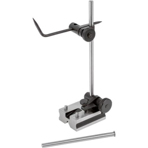
You will need a machinist's surface gauge or a shop-made equivalent. This instrument or some shop-made equivalent will be needed to mark the line of each gundeck which will serve as the baseline for each row of gunports.

1750154626531.png

To make a quick and dirty one, you can use a machinist's square or even a square block of wood. Attach a small piece of square wood to the side of the machinist's square's vertical arm with tape so that a pencil can be held in place on top of the block with the pencil point exactly positioned at the desired height from the level base which is the equivalent of the baseline of the sheer plan.

1. If not already set up on a building board, take a flat board and lay out a line down its length representing the centerline of the hull and from that lay out a few lines crossing this centerline at exactly 90-degree angles. These athwartship lines will be used as reference lines to make sure your gunports are placed exactly the same on each side. If you wish, these lines can replicate the station lines on your plans, but that's not essential. What's important is that they cross the centerline at exactly right angles along the run of the gunports on each side of the hull.

Now, set up your hull securely on this building board or other flat surface making sure the hull is perfectly aligned on the centerline that you have drawn and is perfectly level and plumb. This positioning is critical because all else will be measured from it. If your keel isn't directly on the centerline or the right angle lines aren't exact, your gunports will not be positioned as they should be. (It doesn't matter how high the hull is if the keel isn't resting directly on the base, so long as the keel is parallel to the centerline and the base is level and the hull is level, but if the hull isn't resting directly on the same level plane as your surface gauge or square, be sure to allow for the additional height when setting the distance of each gundeck above the sheer plan baseline.

Important: If your solid hull requires a "false keel" to be added to it, that should be done before you start measuring from the baseboard without the keel attached or all your measurements will be too low by the height equal to the thickness of the false keel that hasn't been added on yet.

2. Set your surface gauge scribe point or your pencil point on the pencil rest on your machinist's square or square block of wood to the distance between the base and a gundeck (again, be sure to add the additional height if the model's keel isn't resting directly on the baseboard or flat surface which is the reference datum for your measurements.)

3. With your surface gauge on your baseboard or flat surface (i.e. the physical baseline of your sheer plan) run the surface gauge's scribe point, or your pencil point, across the side of the hull to mark the run of the gundeck.

4. Repeat for each gundeck.

5. Now comes the tricky part. A machinist's square (or some equivalent, such as a perfectly square suitably sized block of wood) will be used to strike the horizontal and vertical lines representing the top and bottom sills and the sides of the gunports. There are two catches here.


A. The sides of your hull are not flat, but your sheer plan is flat. The hull has tumblehome vertically and is curved running bow to stern, so when marking them you will have to move your pencil or scribe point towards or away from the hull surface to maintain contact with the hull in order to mark it. This will take some care.

B. Because the sheer plan is a two-dimensional (orthographic) projection, if drawn properly, your gunports will not be of uniform size in the sheer plan because the ports are to one degree or another angled into the third dimension, and this will affect their size on the two-dimension sheer plan. As the ports near the bow and the ports tilted along the tumblehome are angled away from the flat plane, that will distort their shapes in the orthographic projection. If this is confusing, think of the gunport as a playing card. If you look at its face straight on, the card's dimensions look like what they would be if you measured its height and width with a ruler. However, if you look at the card and tilt it towards or away from you, it will appear to get shorter than its "flat" measurement. Similarly, if you look at the card face on and then turn it on its long axis towards or away from you, the card will appear to get thinner. This effect will increase or decrease in proportion to the degree of tilt or rotation of the card. Your gunports on the tumblehome will look shorter in two dimensions and those on the curve of the bow will look thinner in two dimensions. (Note that as a practical matter, in a scale model this projected difference is negligible in the area of the flatter sides of a hull amidships compared to the narrowed bow area of the sides of a hull.)

So, if your sheer plan has different sized gunports (more likely most noticeable at the bow) you will have to make sure to correct for width and if they are shorter along the tumblehome, you will have to make sure to correct for height. You should strike a line from the baseline to the deck line for each gundeck and then lay out the height and width of each gunport relative to the actual stated measured dimensions of the gunports and their height above their respective gundeck, not their height and width as drawn on the sheer plan. It is sometimes helpful once the gundeck line is drawn to make (in this case a 3/8" square) template to use to draw the gunports relative to the gundeck(s) and each other.

As you lay out your gunport placements, use the lines that cross the centerline at right angles as reference lines to make sure your gunports are placed the same on both sides of the hull. When laying out the opposite gunport, use your machinist's square and dividers to determine the distance between the sides of the gunport and the nearest reference line. That distance should be exactly the same as that gunport's opposite partner on the other side of the hull.

Additionally, the same principles apply to the spacing of the gunports relative to each other. The distance between gunports is usually equal, but when projected in two dimensions on the sheer plan, the gunports running at an angle along the hull where it curves towards the stem will appear closer together than the gunports on the sheer plan which run along the "flat" of the hull amidships. Here again, space your gunports as any notation indicates, scaling from a rule and not the plans. If you want to double check your accuracy and your plans are laid out orthographically with the half-breadth plan directly above or below the sheer plan, you can construct lines from the sides of a gunport on the sheer plan which intersect that gunport's gundeck outboard edge on the half-breadth plan and the distance between the intersections of the two lines at the gundeck outboard edge on the half-breadth plan will be the actual width of that gunport.

Remember the basic machinist's rule: "Do not scale from the plans." Many professional engineering drawings will have this admonition stamped on them. Professionals who use plans know that the measurements written on the plans are to be transferred from a known accurate scale to the workpiece and the distance is never to be simply transferred from the scaled plan directly with a pair of dividers. This is because the plans can never be drawn with exactitude and even if CAD technology can ensure an accurate length lines on the plans, paper moves, and big pieces of paper move even more than small ones, due to changes in humidity. The notation "one foot" will not change with the environment, but the one-foot-long drawn line may. Now, many modelers will "scale from the plans," using them for templates and so on and in most cases, we can get away with it, but myself I just follow the "no scaling from the plans" rule out of habit from working in larger scales. Measurements are critical when laying out placements of a series of features, and especially so when there are rows of things to be measured. (An inexactly placed gunport sticks out like the proverbial sore thumb.) Cumulative error can easily occur in series of measurements, so I'd urge you not to scale from the plans when laying out gunports.

I hope this will be helpful. It's one of those things that is a lot easier to understand by watching it done that to describe it with words, but it's also one of those things that cause a lot of modelers fits.
 
Last edited:
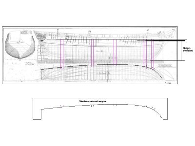
I have never seen a video of laying out gun ports but maybe the drawing below will help. Contact the USS Constitution Museum to ask about acquiring a set of plans. The ones below are taken from the internet and low resolution so not very accurate compared to what they hopefully can offer digitally or on paper. I enlarged them to full size to find approximate dimensions, but seeing how I drew in five of the gun port alignment lines as examples it should give an idea on how to do this. It is merely a drawing version of Bob's nicely detailed explanation. A wooden or cardboard template can also be made to aid in locating the ports.
Allan
Constitution layout of gunports.JPG
 
If you go with this method, I am sure the members will be happy to see how it works out. Hope all goes well. If you do contact the museum you might want to ask Dr. Herzog or Kate Monea for the actual dimensions of the gunports. This could be very helpful. If you do not have their direct email addresses and want to contact them, please feel free to PM me with your email address and I can then send you their direct emails.
Allan
 
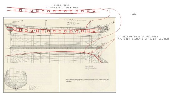
Using Bob and Allen's excellent methods for laying out the gunport locations, here is a drawn example of that paper strip method that can be used in conjunction with their methods of locating the ports. This method simply allows you to remove the paper strip, from the model, after locating the cut-outs, so you can comfortably draw out your gunports on the table rather than on the model itself, which could be a bit awkward. After you're happy with the layout of your gunports, simply tape the paper strip back onto your model and use it as a template to mark or cut out your gunports.

Gunport Cheat.jpg
 
Many thanks for the suggestions to all.
So I have the start of a plan. The model comes with a 1:1 rendering of the plan view and side view. I’m going to have a mirror image printed of the side view and tape both port and starboard to the hull. I have also ordered some 5/16” square tubing to use as a punch(?)(thanks @MThomas)
When all that has been gathered, we’ll try a couple of holes. I also want to build a cannon to see how it works in the space.
I will try to keep everyone updated on my progress, but it’s going to take a few weeks, so bear with me.
And once again, what a buncha great ideas

Jim
 
I’m going to have a mirror image printed of the side view and tape both port and starboard to the hull
Jim,

If I'm understanding you correctly, those 1:1 copies/prints will not fit onto your model properly. The image(s) of the drawing that you will be printing are in 2D, not 3D. Your printouts will be way too short, and your gunports will become 'grossly' misplaced! You'll notice that 'immediately' when you put your print-outs on the hull. That won't work! You need to account for the extra 3D length/geometry created by the curvature of the hull, if that makes sense. The shape of your hull is not a straight, 2D line. That is why I suggest you use the paper strip method, taped to the model, followed by Allan and Bob's methods of locating the gunports on those strips of paper. ;)
 
Last edited:
I don’t know. Maybe so. I’ll only be using a strip encompassing the decks and gunports. If it don’t work, drop back and punt.
Jim
 
If you go with this method, I am sure the members will be happy to see how it works out. Hope all goes well. If you do contact the museum you might want to ask Dr. Herzog or Kate Monea for the actual dimensions of the gunports. This could be very helpful. If you do not have their direct email addresses and want to contact them, please feel free to PM me with your email address and I can then send you their direct emails.
Allan
I sent an e-mail to the museum authorities about the issue and asked for help. I hope everything will be as I expected.
 
Allan, Yes, I received an email.
thank you. I am grateful. These files will be very useful to me. I will put them on transparent acetate, mark the ports and apply them to my model.
 
Back
Top