- Joined
- Dec 1, 2016
- Messages
- 5,956
- Points
- 728

sometimes researching hull framing leaves you scratching your head and wondering WHAT!
just when you think you got it figured out you are thrown a curve ball for example the Royal George designed and built by John Coleman then taken apart as a kit shipped to Canada and reassembled. It is a very nice looking ship so I thought I might draw it out.
first head scratcher is how the framing are identified usually it starts with 0 at midship that is called the flat because there is no bevel. Then forward it is lettered A B C D E etc. to the forward cant frames. then numbered 1 2 3 4 5 6 etc to the stern frames.
look at the Colemans drawing for the Royal George
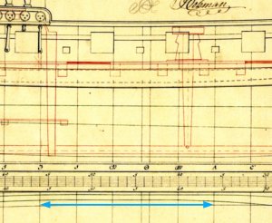
he started with the midship flat with a double line as 0 then forward with B then A and C D E etc aft he went 2 1 3 then 4 5 6 etc WHY?
looking at the other ship Coleman built he did the same thing on the Ontario plan
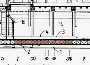
what is going on here the blue arrow on the Royal George between 3 and A are all the same dead flat frame between 3 and B on the Ontario are all the same dead flat frame.
Reason could be both Colemans ships were armed transports so a big belly was needed for cargo space
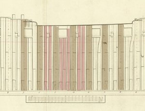
step two any other examples of double frames with fillers and repeated dead flats? yup a frame drawing in the admiralty archives show the same arrangement of close spaced triple frame at mid ship
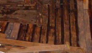
any archaeological support for such framing
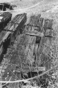
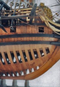
how about placing the midship frames closer together again seems so with the Eagle another great lakes ship

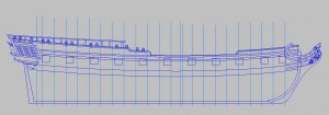
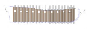
working out a framing plan for the royal George would look like this
just when you think you got it figured out you are thrown a curve ball for example the Royal George designed and built by John Coleman then taken apart as a kit shipped to Canada and reassembled. It is a very nice looking ship so I thought I might draw it out.
first head scratcher is how the framing are identified usually it starts with 0 at midship that is called the flat because there is no bevel. Then forward it is lettered A B C D E etc. to the forward cant frames. then numbered 1 2 3 4 5 6 etc to the stern frames.
look at the Colemans drawing for the Royal George

he started with the midship flat with a double line as 0 then forward with B then A and C D E etc aft he went 2 1 3 then 4 5 6 etc WHY?
looking at the other ship Coleman built he did the same thing on the Ontario plan

what is going on here the blue arrow on the Royal George between 3 and A are all the same dead flat frame between 3 and B on the Ontario are all the same dead flat frame.
Reason could be both Colemans ships were armed transports so a big belly was needed for cargo space
step two any other examples of double frames with fillers and repeated dead flats? yup a frame drawing in the admiralty archives show the same arrangement of close spaced triple frame at mid ship

any archaeological support for such framing

how about placing the midship frames closer together again seems so with the Eagle another great lakes ship

working out a framing plan for the royal George would look like this


