• Win a Free Custom Engraved Brass Coin!!!
    As a way to introduce our brass coins to the community, we will raffle off a free coin during the month of August. Follow link ABOVE for instructions for entering.

I have decided to start over…….

ASA expressly forbids having F1 P
Sorry Dean, but I haven't the slightest idea what this means.:( Who/what is ASA and what does the P stand for? For ASA I found everything from the third king of Judah to American Society of Anesthesiologists so am at a loss.
Thanks
Allan
 
rolls of copper 1MM thick
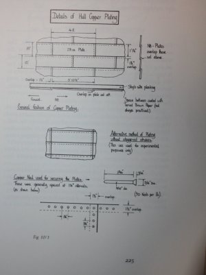
1mm is just about spot on for full scale assuming 28 ounce plate. For our scales, it would of course be much thinner. In case you do not have it, the following is from The Construction and Fitting of the English Man of War, page225 which you may find helpful. 28 ounce plate at 1:48 scale would be about 0.02mm thick. Maybe also check my math, just in case.:)
Allan
1759745852515.jpeg
 
The ASA was The American Shipmasters' Association. It was that name in 1870 and 1885. In 1903 The American Bureau of Shipping. Rules for insurance on ships, slang had as the American Lioyds. P is port .

Reading the 1870 rules : Floor Timbers section 10 The length of floor timbers amidships should not be less than three-fifths the breadth of beam. Long and short armed floor timbers are preferable, and in flat-bottomed vessels should always be used. These must lap each other one-third of their length in the body of the vessel, and one-fourth at the ends. If first futtocks are used they must always butt close on the keel, the laps of the timbers to be not less than one- eighth of the breadth of beam.

It seems that I mis-remembered the source of the never butt over the keel rule. I thought that the 60% of the beam rule for floor timbers came from a much older source.

Dean
 
"Need to place frames on the deadwood."

"Is it possible to construct the model with the frames/locations as drawn or with some intermediate, or is it essential to make all the 12.5” frames and pack them in solidly?"

"I have read that measurements from the stern frame sections intersect the deadwood (not sure I get this!) can derive the bearding line."

The usual method is to have a stem/apron - keel - keel/deadwood - sternpost as a starting unit. Where the deadwood begins the frames go from being full cross frames to being half frames that butt against the deadwood on both sides. I think that "intersect" may mean that a channel was cut into the deadwood as a socket for the heels of the frames. Something that a router or dido blade would do now? On a model, I am not sure that the difference between a simple butt and a routed channel can even be seen. An easier way would be to have the actual deadwood be lower - have it stop at the bearding line - use full cross frames all the way to where the cant frames start - or go full on stylized and use full cross frames all the way to the sternpost = no cant frames to futz with. Do the same at the apron. The cost is having to remove much more wood to get the bevel. The gap between the frames would be filled with a vertical pseudo deadwood piece of wood that is the width of the keel/deadwood. The grain would be perpendicular to the direction of actual deadwood grain - but can the difference be seen? Fake it rather than do it as far as what is deadwood in the way of the frames.

The width of the keel tapers to the stem ( the stem also has a really serious taper and one that is dynamic. By which I mean that knife edge at the figurehead is more narrow than the knife edge at the waterline, ) -
There is a similar taper to the sternpost. It is not a continuous taper. It stays unchanged until it gets sorta near to each end. I do not remember seeing a rule about where the taper begins. I would not taper the deadwood or apron with the keel. The frame heel stops when its pattern width is the full keel width. This is what the bearding line is. The long (and gets longer) taper from the bearding line down to the rabbet at the keel is adzed out of the deadwood. The actual frame stops far short of where its pattern shape shows it to be,

The floor is 12.5" wide, The half floor is 12.5" wide. They all touch. F1 is something like 11" wide. F1 butts on the half floor and then floats free in space. F3 is scarphed to F1. It starts at the same 11"(?) and tapers - which would be maddening to replicate. It is behind the topside planking anyway. F2 looks to be something like 9-10" wide. It butts on the floor timber end. It floats in space too. F4 looks to be 8-9" wide and butts on the end of F2, Also behind topside planking. This pattern is purely functional. Are you sure that you want to exactly replicate this?

I would make the frame on either side of each station line be 12.5" wide all the way and bond the two into a bend. The overlap solves the weak end grain to end grain bond problem (which is actually a non-bond). Omit the two frames in the middle. You can fit a thin piece of wood that is keel width - on top of the keel in the space between each bend. This will make for a stronger bond to the keel for the bends and it will look like you either notched the top of the keel or the heel of the bend. It will avoid any troublesome notch milling in the actual keel. Lowering the river instead of raising the bridge as it were.

Dean
 
Dean, thank you so much for taking the time to reply. I confess I am out of my depth! My take always from your comments are:-

Don’t taper the frames at the top. if they are full size they will be covered by the top side timbers.

What is an apron?

I still cannot get how to establish the vertical height of the frames. Could I measure from the top of the keel? The top of the deadwood? Or even the height of the water lines?

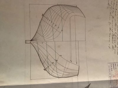
Below I post the sections. The only datum is the keel and the waterlines.

IMG_1010.jpeg

thanks to Dean, Allan teal for your continued support and guidance…..SS
 
SS.

An apron is essentially the deadwood at the bow. The frame bevel there makes cant frames important. Cants are half frames. Their heals need something to fix to. The apron is it - unless I am not remembering the name for this zone correctly.

With a model - we do not have the physical limitations of our wood that ruled a full size hull. Having full frames go all the way to the hawse timbers is not a problem. There is a lot of wood to remove to get the bevel. I do as many as eight frames as a unit and the last unit usually has a really impressive volume of wood to remove. It is far more than what is left for the frames.

You are dealing with singleton frames. I would never try to position them using internal locators. I would use something external. I would draw a horizontal line across all of the frames that was close to rail level. A jig that is a rigid board mounted up t the line level provides an external alignment locator. The board needs to be hollowed to let the frame tops through. This is a straight forward method. Notches are not necessary. Battens can be glued to the jig. Hahn did something similar by extending the tops of every frame extend above any of them to a common horizontal level. He built his hulls upside down. That high level line then became the baseline. Jigs are your friend. Jigs are probably necessary. Unless you are Graham Chapman building a ship model in bed and in the dark.
 
Continue to mull all this advice over, whilst experimenting with possible frame manufacture and adjustments. Also bringing my vessels construction details from first proposals to commissioned vessel, ready for first sailing to fruition to understand its history. Now evaluating key voyages for study.

Thanks SS
 
Just a quick question on ZAZ6157 above. The red line on the elevation, is the top of the deadwood as the mast steps are shown baring down on this.

If this is correct I have the rabbet line (at least from the bow to the midships frames as they raise to the stern as well as the deadwood.

Any advice on estimating bearding line please.

Thanks all followers SS
 
Back
Top