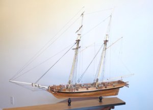
Building the Invincible, a Baltimore clipper, Part 1
This is a build history rather than a build log since the model was completed in 2019. It will not be a detailed step-by- step account, but instead I have just outlined some of the methods that have served me well in scratch building plank on bulkhead models. This is my first attempt at posting to this Forum, so I will take it a bit slowly and do it in parts.
Invincible History
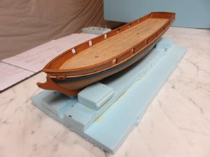
In October, 1835 colonists in Texas started a rebellion against Mexico to form their own state. Shortly afterward, the Provisional Government, recognizing the importance of protecting the coast, authorized the formation of a Navy which was born in January 1836. The fleet consisted of all of four vessels, three purchased schooners and and a former U.S. Revenue Cutter ( More information on Texas Navy history can be found on the web site of the Texas Navy Association. ). One of the vessels, the schooner Invincible, was of particular interest as a model for display at the Houston Maritime Museum since a search is currently underway off Galveston for her wreckage, and I agreed to build the model.
Hull Design
Although no plans exist for this ship, original purchase documents indicate that she was built in Baltimore, probably as a slaver, at the yard of John A. Robb, and had the dimensions 66'3” length on keel, 83'8” length on deck, 21' beam, 8' depth and 126 tons. Invincible was most certainly a Baltimore clipper design. The total cost in 1836 was $20,000: $12,613 to the Robb shipyard and about $7,400 for fitting out.
Robb was a prolific shipbuilder with a long career and the subject of a detailed biography by G.M. Footner in the Nautical Research Journal (Vol. 50, No. 3, page 130, 2005 ). In this article Footner provides the plans of another Robb designed Baltimore clipper, smaller than Invincible at 75' length and 19' beam. In Howard Chapelle's book, “The Search for Speed Under Sail “ (Bonanza Books) , he presents (page 294 ) a plan for the the Isabella, which has very similar dimensions to the Invincible, the only significant difference being a 19' breadth as compared to a 21' breadth. A comparison of the plan for the Isabella with Footner's plan of a Robb schooner indicates very similar lines so it was decided to base the Invincible model on the Isabella since the dimensions are so similar. Only the deck arrangements were altered to match what was known about the Invincible.
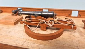
The armament on the Invincible at commissioning is known from the original documents and consisted of 4 cannon on each broadside ranging from 4 to 6 pounders and an 18 pounder central pivot gun.
Masting and Rigging
Mast and spar dimensions were based on data for the Robb designed schooner Allicope (C. Cozewith, Nautical Research Journal, Vol.63, No.2, page107, 2018) which was similar in size to Invincible. The schooner rigging plan in Petersson's “Rigging Period Fore and Aft Craft” (Naval Institute Press, 2007) was the primary source for this model. Determining rigging sizes is usually a challenge for a scratch builder. I utilized the tables in Biddlecombe 's “The Art of Rigging” (Dover Publications, 1996) for some of the lines and the rest were estimated from the rules of thumb in Lee's “The Masting and Rigging of English ships of War, 1625-1860” (Naval Institute Press, 1979) which allows calculation of line sizes if the mast dimensions are known.
Construction
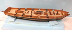
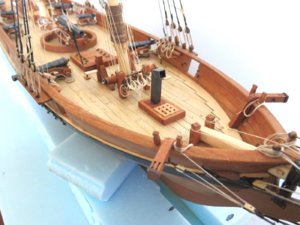
Invincible was built by the plank on bulkhead method at a scale of 1/50. The Chapelle plans were enlarged on a copying machine to give the desired model dimensions.
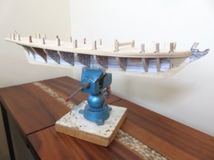
Figure 1 Keel Piece and Bulkheads
The lines of the sheer plan were altered as follows to make a template for the keel piece:
1)The line for the underside of the deck was lowered by 1/32” to account for a sub-deck on the model.
2) Slots were indicated for the masts
3)Temporary extensions were drawn at the stern to help shape the curve of the transom and at the bow to support the ends of the bulkhead planks.
A bulkhead template was made for each station on the body plan. These templates were lined up with the shear plan to establish the location of the deck at the centerline, and a cambered deck line was then drawn on each bulkhead template. The templates were glued to 3/16” aircraft plywood for keel piece and bulkhead construction.
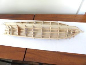
Figure 2 Frame Assembly
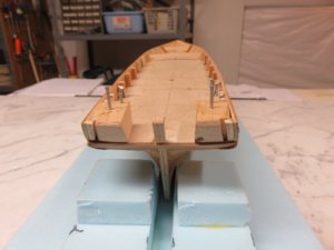
Before inserting the bulkheads into the keel piece, holes were drilled in the bottom for later attachment of the pedestals and slats were glued on each side of the masts slots to insure proper mast placement when they were inserted. Note in Figure 2 some wood has been removed at the stem rabbet line so the plank ends will lie flush with the keel piece.
Alignment was checked by making sure the waterlines on the bulkhead templates lined up with the waterlines on the keel piece during dry fitting. After alignment adjustment, the bulkheads were glued in place then faired. Next, filler pieces were made and glued in forward of the first bulkhead and aft of the last bulkhead to support the ends of the hull planking.
The next step was to cut out a sub-deck from 1/32” aircraft plywood. Prior to installing it, the location of the deck edge was marked on the outer edge each bulkhead and a notch was cut into the bulkhead for a 1/16” x 3/32” stringer. The stringer was test fitted to give smooth curvature of the deck from bow to stern and then glued in place. Finally, the sub-deck was glued to the top of each bulkhead and the stringer. This will insure the proper shape for the deck.
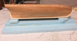
The model received double planking of 1/16” basswood followed by 1/32” cherry. Plank maximum width was 3/16”. A decision for the modeler is where to start planking. I usually choose to put the first plank either at the wale or right below the gun ports where it can serve as a reference for later measurements on the hull. For the Invincible, the first plank was at the wale.
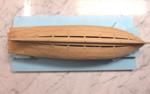
Figure 3 Planking Scheme
There are many different well documented approaches to planking. I'm sure that my procedure is similar to many others. I first measure the perimeter of the dead flat (widest) bulkhead below the wale and divide by the plank width, in this case 3/16”, to get the number of planks needed to cover the hull from the wale to the keel. Marks are then placed on the dead flat bulkhead corresponding to bands of 4 or 5 planks (3/4” or 15/16”) and battens are tacked on just below these marks. The battens are then adjusted by eye to give fair plank runs with the requirement that the width of a band at the stem be no less than ½ the width at the dead flat bulkhead. When satisfied, the battens are then tacked to each bulkhead and their position marked before they are removed. Starting with the uppermost band, the perimeter along all of the bulkheads is measured from the wale to the first batten marks and divided by the number of planks in the band. This quotient is multiplied by the plank width to get the width needed at that bulkhead. The planks are then tapered accordingly and glued to the bulkheads and to the edge of the plank above. The same measurement and tapering method is used from band to band.
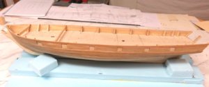
Figure 4 Lower Planking and Bulkheads
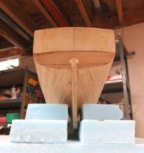
For the final band, I put the garboard on first and planked upward to complete the lower planking. No stealers were needed for this particular hull which had very gently curved lines. Lastly the bulkhead area is planked up from the wale to the sheer. This region of planking requires little tapering and usually presents no problem.


