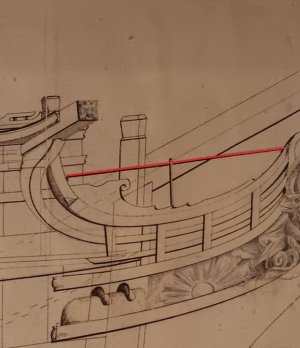
Paul …… what is the fun of a simple ‘plug and play’?While I don't think the headworks are the hardest thing I have done on this ship model (hawse timbers still hold that place of pride), they are making a case for their inclusion near the top of that list.
The problems are legion - but counted among them are the many planes of space that need to be simultaneously balanced (nothing is square) - and the fact that nothing should be fixed (glued) until future components are fabricated. Indeed, TFFM (Antscherl) suggests that fabricated parts just be pinned in place and then everything is taken apart later in preparation for final assembly. I am aware of three swan class ship builds that followed this model precisely.
As it turns out you are not reading a fourth.
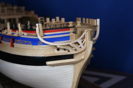
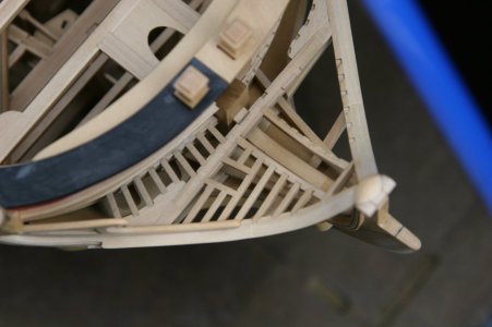
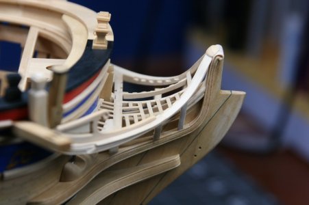
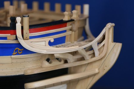
Following the permanent installation of the upper and lower cheeks (no problem with doing that) comes the fabrication of the main rail. Antscherl dedicates several pages to this complicated piece but then says to just pin it in place while you fabricate the head beam (runs athwartships just like a deck beam) and the knees (just like lodging knees). And then go ahead and fabricate some carlings that terminate at a crosspiece (hey you, do NOT touch that bottle of glue). Next, make a lower rail which has to be precisely fit in place so that you can fabricate the head timbers (several more pages of instruction) which it passes through. Whatever you do DON'T glue anything yet.
Now, take everything apart and glue it all in place in reverse order.
Well, "that dog don't hunt" (an American colloquialism that my international friends will hopefully take the meaning of).
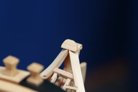
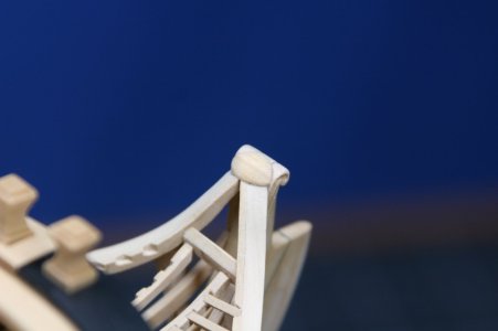
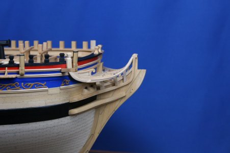
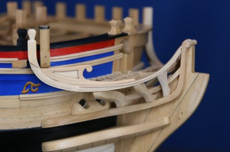
The main rail was fabricated and pinned in place (I was still following the instructions at this point):
View attachment 492907
View attachment 492908
View attachment 492909
View attachment 492910
It was during the fabrication of the head beam that I realized this "fit it in place and glue it together later" approach wasn't going to work for me. I permanently cemented the main rails and carried on...
In the following image you can see the athwartships head beam - the carlings - the crosspiece (forward end of the carlings) and notched battens attached to the hull:
View attachment 492912
So far so good.
But then it came time to fabricate and install the head timbers. There were four of these on the Pegasus (that's the sample ship highlighted in TFFM) but only three on the Kingfisher. The head timbers sit on the upper cheek and support the main rail.
View attachment 492914
Not only do the head timbers sit on the upper cheek, but they should also sit over the top of (saddle over) the standard that sits on the knee of the head. The problem is you can't install these parts if you have cemented other things in place...
My solution (and in fairness, a solution that I did not invent) was to cut the head timbers into two pieces. I did attempt to make these appear as if they were a single piece via scarf joints, but that was a comprehensive failure.
These six little pieces represent a full day of work...(really Paul? a FULL day? Yes, an eight hour day on these six pieces and I don't even know yet if they will be usable until I sort out the lower rail...).
View attachment 492913
And now I need to figure out how to run a lower rail through these head timbers.
I should have chosen a different hobby: maybe gardening, or genealogy... my dad collected coins...
The front of this kind of ship is complex and a real challenge. Thinking one step ahead is in your position not enough. Not with your model and not in your profession. I'm pretty sure you can tackle this 'problem' with your project-based approach.
And with a (small) re-do you earned a coin for you jar. That almost in the footsteps of you dad’s collection ……..

PS: I feel very very honored that you mentioned my current build. You made me blush.
Regards, Peter


