• Ships of Scale has incorportated an extra level of security when you log In. Please follow on-screen prompts to acknowledge that you are not a robot via a "Check Box" or a "Pictorial Check Box Puzzle". This is needed due to higher level of AI Activity Security.
  • SUBSCRIBE TO SHIPS IN SCALE TODAY!

    The beloved Ships in Scale Magazine is back and charting a new course for 2026!
    Discover new skills, new techniques, and new inspirations in every issue.

    NOTE THAT OUR NEXT ISSUE WILL BE July/August 2026
  • Win a Free Custom Engraved Brass Coin!!!
    As a way to introduce our brass coins to the community, we will raffle off a free coin during the month of August. Follow link ABOVE for instructions for entering.

Le Requin 1750 - ZHL POF Kit

No further physical progress at this time. Before starting the hull framing I have been cross-checking transverse frame dimensions against the slots in the construction jig plate B, as an earlier spot check had shown up some discrepancies.

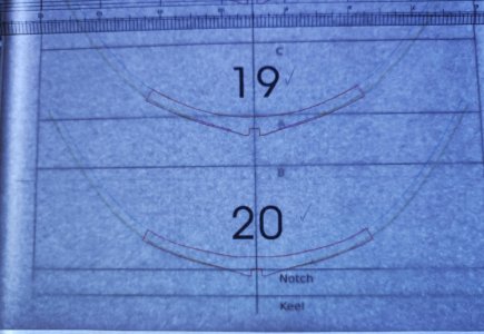
I drew a grid on an A4 sheet with a vertical centreline and horizontal lines at the heights of the top surfaces of the various jig plates. I put this on an LED lightbox and overlaid each ZHL frame drawing in turn. I then used this to measure the widest breadth of each of the frames (full breadth port to starboard) at the elevation of the top of jig plate B (5cm above base board). This is for Frame 20 as an example:

Lightbox(1).jpg

To allow a comparison with the above, I also measured the actual transverse dimensions of each frame slot on jig plate B, measuring port to starboard at the widest part of each slot (aft face for frames forward of midships and forward face for frames aft of midships).

At this stage I have only checked jig plate B as this covers most of the midships area, and I’ll address the other jig plates as I get to them.

Using the lightbox, I also overlaid each ZHL frame drawing onto the corresponding Ancre frame drawing to identify discrepancies. Most matched reasonably well but some were noticeably different (wider) in way of the first futtocks. The greatest deviations were for Frames 21-29 and 38-43 (3-4mm per side), while Frames 31-34 were less (1-2mm per side).

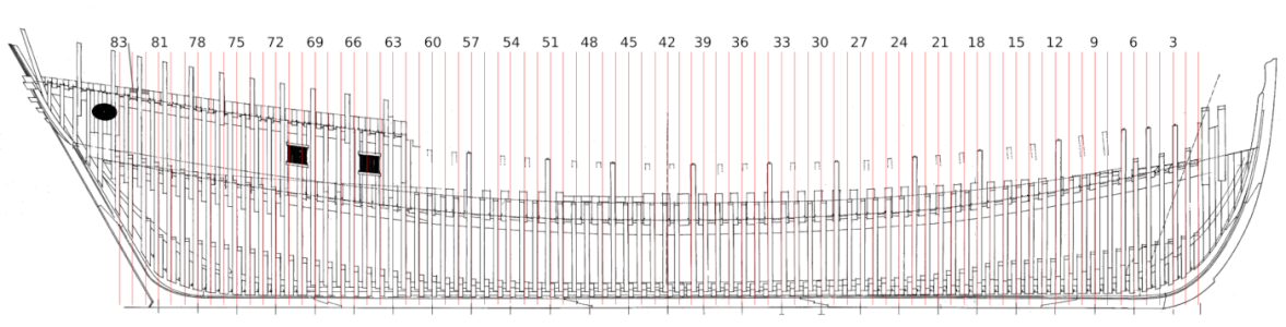
The CD with the kit included a copy of the Ancre framing profile, which I imported into Inkscape (a vector graphics editor). I drew in vertical guide lines at the widest part of each frame (aft face of first futtocks forward of midships and forward face of first futtocks aft of midships):

Frame Check Grid .png

All of the following plots are produced using Inkscape using the above as a framework, but note that the vertical scale of each plot is different to the horizontal scale.

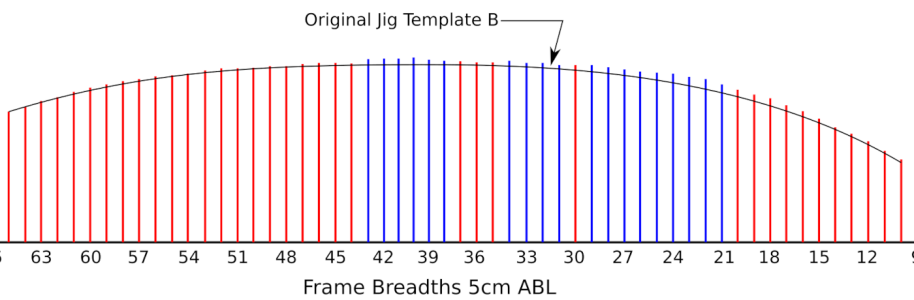
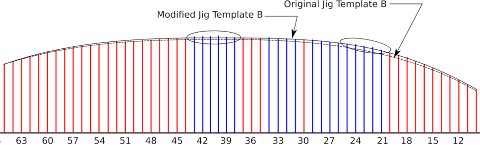
I plotted the widths for each frame as shown in the following, where the lengths of the vertical lines represent the measured width (port to starboard) of each frame at 5cm above base board. The red lines indicate the frames which have close agreement between the kit and Ancre, and the blue lines indicate the frames where the ZHL frame drawings differ from the Ancre drawings as noted above. The curve represents the actual measured outboard profile of the slots in jig plate B:

Frame Check 5cm .png


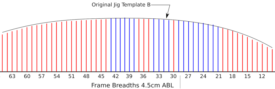
This shows a lack of fairness in the ZHL frames mainly in way of the blue lines, and also shows that the jig plate is either too high or the slots are not cut far enough outwards. The jig plate height was set using the provided templates, so ought to be correct. To check the effect, I repeated the exercise with the frame measurements taken at 4.5cm above base board:

Frame Check 4.5cm .png


This is too low, as this results in clearances between the frames and the slots.

I decided to keep the jig plate B at 5cm above base board and to modify the slots. I will be modifying the slots anyway to square their outboard ends to be fore-aft rather than having them follow the original faired shape so it is easy to combine this with adjusting the slot depths. This squaring off is for two reasons; because I won’t be fairing the outside till the hull is completely framed and reinforced inside and I don’t want to fair just one part of each frame to get it to fit the jig, and also because I prefer to keep as much material as possible till fairing.

This is the final arrangement I came up with. The modified jig plate slot profile is developed by generating a smooth curve constrained to 16.8cm full breadth at 5cm elevation at midships, as measured off the Ancre body plan, and as closely aligned with the ends of the frame lines as practical except for the frames obviously out of fair, which are shown circled below:

Frame Check New Template .png

The adjustments needed to the jig plate slots for each frame are derived within Inkscape. From measurements, the maximum adjustment occurs at Frame 22 and is about 3mm each side.

When going through the same exercise for the other jig plates forward and aft, any modifications will be checked against the above to maintain fairness longitudinally. During frame construction, any frames misaligned with the modified jig slots will be adjusted to suit when assembling so that frames rest against the slots rather than being sprung in or pulled out to avoid locking in stresses, which could result in distortion when the hull is released from the construction cradle. I bought spare 3mm sheets from ZHL shortly after buying the kit, mainly in case of damaging the frames but these can also be used to rebuild any frames which do not fit.

So, the next step is to temporarily dismantle the jig to allow the slots to be modified.

Ken
 
Hi Ken, your jig analytics sounds solid, I will be looking forward to your as built results. The small discrepancies you are defining at this stage should pay huge dividends during construction. I found the jig to be mismatched more so toward the bow and stern rather than the center section however I never looked at it like you have.
 
Hi Ken, your jig analytics sounds solid, I will be looking forward to your as built results.

Hi Daniel. So will I. Hopefully I will not be making things worse!

I think that one reason the centre section seems OK is because the frames are relatively flexible compared with the ends.

I am surprised at the apparent discrepancies in fairness across frames, and between frame drawings and construction jig templates. I previously assumed that the kit was modelled using a faired 3D computer model, which in turn was used to produce the laser paths for the components and the drawings. But maybe not.

So I'll see what is in store. Thank you for your interest.

Ken
 
No further physical progress at this time. Before starting the hull framing I have been cross-checking transverse frame dimensions against the slots in the construction jig plate B, as an earlier spot check had shown up some discrepancies.

I drew a grid on an A4 sheet with a vertical centreline and horizontal lines at the heights of the top surfaces of the various jig plates. I put this on an LED lightbox and overlaid each ZHL frame drawing in turn. I then used this to measure the widest breadth of each of the frames (full breadth port to starboard) at the elevation of the top of jig plate B (5cm above base board). This is for Frame 20 as an example:

View attachment 631455

To allow a comparison with the above, I also measured the actual transverse dimensions of each frame slot on jig plate B, measuring port to starboard at the widest part of each slot (aft face for frames forward of midships and forward face for frames aft of midships).

At this stage I have only checked jig plate B as this covers most of the midships area, and I’ll address the other jig plates as I get to them.

Using the lightbox, I also overlaid each ZHL frame drawing onto the corresponding Ancre frame drawing to identify discrepancies. Most matched reasonably well but some were noticeably different (wider) in way of the first futtocks. The greatest deviations were for Frames 21-29 and 38-43 (3-4mm per side), while Frames 31-34 were less (1-2mm per side).

The CD with the kit included a copy of the Ancre framing profile, which I imported into Inkscape (a vector graphics editor). I drew in vertical guide lines at the widest part of each frame (aft face of first futtocks forward of midships and forward face of first futtocks aft of midships):

View attachment 631456

All of the following plots are produced using Inkscape using the above as a framework, but note that the vertical scale of each plot is different to the horizontal scale.

I plotted the widths for each frame as shown in the following, where the lengths of the vertical lines represent the measured width (port to starboard) of each frame at 5cm above base board. The red lines indicate the frames which have close agreement between the kit and Ancre, and the blue lines indicate the frames where the ZHL frame drawings differ from the Ancre drawings as noted above. The curve represents the actual measured outboard profile of the slots in jig plate B:

View attachment 631457


This shows a lack of fairness in the ZHL frames mainly in way of the blue lines, and also shows that the jig plate is either too high or the slots are not cut far enough outwards. The jig plate height was set using the provided templates, so ought to be correct. To check the effect, I repeated the exercise with the frame measurements taken at 4.5cm above base board:

View attachment 631458


This is too low, as this results in clearances between the frames and the slots.

I decided to keep the jig plate B at 5cm above base board and to modify the slots. I will be modifying the slots anyway to square their outboard ends to be fore-aft rather than having them follow the original faired shape so it is easy to combine this with adjusting the slot depths. This squaring off is for two reasons; because I won’t be fairing the outside till the hull is completely framed and reinforced inside and I don’t want to fair just one part of each frame to get it to fit the jig, and also because I prefer to keep as much material as possible till fairing.

This is the final arrangement I came up with. The modified jig plate slot profile is developed by generating a smooth curve constrained to 16.8cm full breadth at 5cm elevation at midships, as measured off the Ancre body plan, and as closely aligned with the ends of the frame lines as practical except for the frames obviously out of fair, which are shown circled below:

View attachment 631459

The adjustments needed to the jig plate slots for each frame are derived within Inkscape. From measurements, the maximum adjustment occurs at Frame 22 and is about 3mm each side.

When going through the same exercise for the other jig plates forward and aft, any modifications will be checked against the above to maintain fairness longitudinally. During frame construction, any frames misaligned with the modified jig slots will be adjusted to suit when assembling so that frames rest against the slots rather than being sprung in or pulled out to avoid locking in stresses, which could result in distortion when the hull is released from the construction cradle. I bought spare 3mm sheets from ZHL shortly after buying the kit, mainly in case of damaging the frames but these can also be used to rebuild any frames which do not fit.

So, the next step is to temporarily dismantle the jig to allow the slots to be modified.

Ken
I just kept up your build-log, Ken. It is interesting to see how you explain and visualize the adjustment for the jig, where you can potentially tackle the 'problems' encountered by others. I also discovered for myself that alignment via a ‘Vector program’ provides clarity. I will follow your build with interest, like I also do with Daniel's.
Regards, Peter
 
It is interesting to see how you explain and visualize the adjustment for the jig, where you can potentially tackle the 'problems' encountered by others. I also discovered for myself that alignment via a ‘Vector program’ provides clarity. I will follow your build with interest, like I also do with Daniel's.
Regards, Peter

Thank you Peter for the comments and interest. I have just finished marking up the jig for the modifications so should be able to start this over the next week.

Daniel's log is a great help.

Thanks. Ken
 
The slots in jig plate B have been modified as described above, and the build cradle reassembled.

But before starting the frames, I made another dimensional check by comparing the transverse distances between the faired, modified, jig slot ends with the frame widths at the jig plate elevation as measured from the ZHL templates to identify the remaining discrepancies. The half difference between these gives the theoretical gap each side between frame/jig slot if the frame is narrower, or the extent to which the slot pushes the frame inwards if the frame is wider.

I arbitrarily set a discrepancy tolerance of ±0.5mm, on the assumption that any discrepancy smaller than this could be accommodated by pulling the frame out with rubber bands or springing in, as applicable, without imposing significant stresses on the hull structure. The plan is to assemble the floor/futtock joints of these frames first with Titebond, then assemble the remaining out-of-tolerance frames initially with reversible glue (Old Brown liquid hide glue), and check their fit and fairness by using flexible battens spanning the surrounding good frames. Hopefully most can be accommodated by intentionally miss-aligning the floor/futtock joints to match the jig slot width and still have enough material left to fair the hull. If not then I have spare sheet stock to rebuild the affected frames. Once fit is confirmed then reglue the out-of-tolerance frames with Titebond.

At this stage the frames will not be faired internally or externally, both to keep material for the final hull fairing and also to keep consistent contact points for the flexible battens referred to above, as the battens will ride on the back edges for the forward frames inside and the front edges for the forward frames outside, and vice versa for the aft frames. Any pre-fairing would probably introduce inconsistencies.

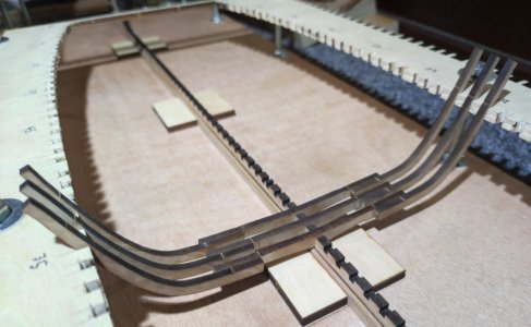
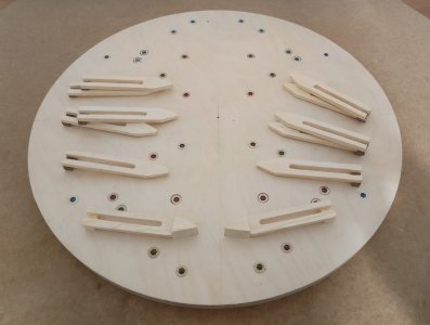
This is the frame assembly jig, prepared based on the one used by Daniel Forlani for his scratch build of Le Requin, as shown in his build log on the Gerard Delacroix French forum, but with the addition of guide stops. The jig comprises a piece of scrap 19mm birch ply ( there is no significance to the round shape. This is an offcut from another project) with M6 threaded inserts and bolts, slotted clamps and with the two guide stops shown at the front.

Frame assembly jig.jpg


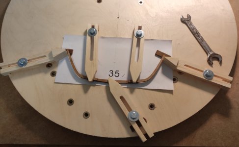
This is the jig as used for Frame 35. Because the futtocks are elevated above the template surface by the thickness of the floor timber there is a risk of introducing errors due to parallax. The guide stops are clamped at the correct positions on the template prior to fitting up the futtocks, allowing each futtock to be positioned correctly while glueing the joint.

Frame 35 Assembly.jpg


For use, the templates are photocopied from the ZHL originals to avoid damaging the originals. There are two problems to note. The light blue colour used for the futtocks does not copy well and needs the contrast turned to maximum. The yellow for the fairing does not show up on the copies at all but as I am ignoring these this is not a problem. Also, photocopying introduces some slight shrinkage in the scanning direction of the copier. The ZHL page for the templates for frames 35-37 are printed landscape, but by copying portrait the shrinkage over each individual frame template is effectively unnoticeable. The best orientation for copying other templates will need to be checked in each case, depending on the aspect ratio of the frames and the way they are printed.

This is the fit up up of Frames 35, 36 and 37. I started with the easy ones first from midships then will work forward and aft, at this stage skipping the out-of-tolerance frames as noted above.

Frames 35-37.jpg

The slots in the keel and floor timbers need to be opened up for fit-up as they are too tight as supplied. Other Requin builders have commented on the keel hogging, and upon advice from @Daniel20 and @dockattner I have screwed the keel to the baseboard. But this does not necessarily mean that the keel will not hog when the hull is released from the cradle. One potential cause is too tight joints between the floor timber and keel slot. In this case, the floor timber will try to push the adjacent “teeth” in the keel apart. Repeating this eighty odd times will result in the top section of the keel trying to expand compared with the bottom section, potentially leading to hogging of the keel.

To mitigate this, and prior to gluing the frame parts together, I opened up the keel slot for each frame using the floor timber upside down as a guide to getting a comfortable sliding fit of the floor timber into the keel slot, in isolation without being affected by any tightness in the floor slot itself. Once the keel slot was opened sufficiently, I turned the floor timber over and opened up the floor slot to a fairly tight sliding fit over the keel, knowing that the keel slot was looser.

Another issue I have found so far for Frames 35-37 is that the lengths of the frame section materials provided differ slightly from those on the template drawings, and the marks on the floor timber supposedly showing the inboard end of the futtocks are about 3-4mm too far inboard, which can be seen on the frames above. I checked these three frame templates against the Ancre framing profile, and the tops of the futtocks in the template drawings match the heights above keel from Ancre. So I aligned the futtocks from the top down, and ignored the markings on the floor timber. This will be the process going forward. At this stage, the frames are not glued to the keel to allow them to be removed for adjustment.
 
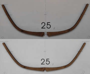
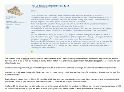
I have been working on the frames forward of midships. But there is an issue with the double floored frames from Frame 26 forward. According to Ancre these are built up with a full floor for the aft “slice”, the port and starboard futtocks and a half floor for the forward “slice” fayed to the full floor and spanning the gap between the heels of the port and starboard futtocks so that the forward slice appears solid. The kit simplifies this by providing port and starboard futtocks which are supposed to meet at the keel. However, they are too short. If the tops are aligned to the top of the template there is a gap at the bottom. If they are aligned at the bottom the tops are too low. Also the futtock profiles better match their templates when aligned at the top rather than at the bottom:

Fr 25.png


The tops of the futtocks in the template drawings match the heights above keel from Ancre and are intended to align with the underside of the gundeck, so I aligned the futtocks from the top down. The gap at the keel could be corrected by squaring off and inserting a filler piece using the spare material from the frame blank. But there is an alternative.

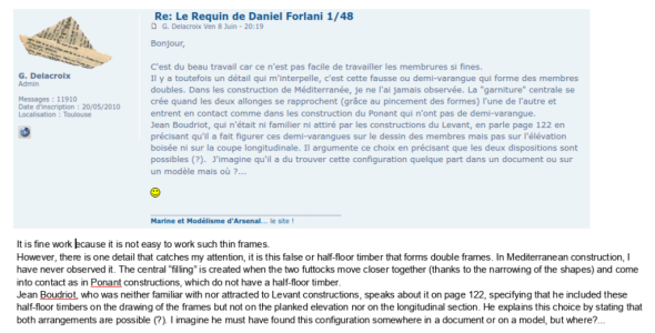
In Daniel Forlani’s scratch build Requin log on Gerard Delacroix’s forum, there is some correspondence from Gerard Delacroix saying that in his experience such half floors are not used in Mediterranean construction and that they should not be present. This is the relevant correspondence. For context, Daniel Forlani’s responses, the initial image prompting this and the discussion is on Page 3 of https://5500.forumactif.org/t3214-le-requin-de-daniel-forlani-1-48:

GD_DF 1.png

GD_DF 2.png


I don’t have the knowledge of Mediterranean construction to determine what is correct or not. but I decided to defer to Gerard Delacroix’s view and leave the half floors out.

I modified the futtocks by cutting them back to give a 20mm overlap with the full floors as measured on the templates, but as the actual floors are about 3mm narrower each side than their templates, the overlap ends up as about 17mm which is similar to what is shown in the Ancre frame templates.

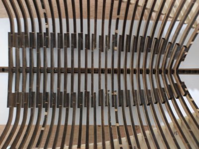
This is the result. I will need to plug the gaps in the affected keel slots and keelson. One other noticeable problem is that the ends of the floors and the ends of the futtocks are uneven.

Forward frames.jpg


Most of this is due to lack of dimensional consistency in the provided floors and futtocks, both from frame to frame, and also deviations between the laser cut members and their corresponding templates, as I have not trimmed any ends except as noted above. But some is probably due to builder error. I will address this when all frames are complete but before glueing them to the keel by using flexible battens to line out fair curves and trim the floor and futtock ends to suit.

Ken
 
I have been working on the frames forward of midships. But there is an issue with the double floored frames from Frame 26 forward. According to Ancre these are built up with a full floor for the aft “slice”, the port and starboard futtocks and a half floor for the forward “slice” fayed to the full floor and spanning the gap between the heels of the port and starboard futtocks so that the forward slice appears solid. The kit simplifies this by providing port and starboard futtocks which are supposed to meet at the keel. However, they are too short. If the tops are aligned to the top of the template there is a gap at the bottom. If they are aligned at the bottom the tops are too low. Also the futtock profiles better match their templates when aligned at the top rather than at the bottom:

View attachment 644103


The tops of the futtocks in the template drawings match the heights above keel from Ancre and are intended to align with the underside of the gundeck, so I aligned the futtocks from the top down. The gap at the keel could be corrected by squaring off and inserting a filler piece using the spare material from the frame blank. But there is an alternative.

In Daniel Forlani’s scratch build Requin log on Gerard Delacroix’s forum, there is some correspondence from Gerard Delacroix saying that in his experience such half floors are not used in Mediterranean construction and that they should not be present. This is the relevant correspondence. For context, Daniel Forlani’s responses, the initial image prompting this and the discussion is on Page 3 of https://5500.forumactif.org/t3214-le-requin-de-daniel-forlani-1-48:

View attachment 644104

View attachment 644107


I don’t have the knowledge of Mediterranean construction to determine what is correct or not. but I decided to defer to Gerard Delacroix’s view and leave the half floors out.

I modified the futtocks by cutting them back to give a 20mm overlap with the full floors as measured on the templates, but as the actual floors are about 3mm narrower each side than their templates, the overlap ends up as about 17mm which is similar to what is shown in the Ancre frame templates.

This is the result. I will need to plug the gaps in the affected keel slots and keelson. One other noticeable problem is that the ends of the floors and the ends of the futtocks are uneven.

View attachment 644117


Most of this is due to lack of dimensional consistency in the provided floors and futtocks, both from frame to frame, and also deviations between the laser cut members and their corresponding templates, as I have not trimmed any ends except as noted above. But some is probably due to builder error. I will address this when all frames are complete but before glueing them to the keel by using flexible battens to line out fair curves and trim the floor and futtock ends to suit.

Ken
Ken, I've already spent several hours sanding out the inconsistencies on my ship. I suspect your diligence will pay you back well in time saved sanding.
 
Ken, I've already spent several hours sanding out the inconsistencies on my ship. I suspect your diligence will pay you back well in time saved sanding.

Daniel, I am not so sure about this. In addition to the differences in floor and futtock lengths noted above, I can see slight differences in the shapes of the laser cut members compared with the templates when overlaying them. Consequently it is a bit of a best guess regarding relative positioning when assembling the frames. So I have my doubts about the accuracy of the lofting and it seems likely that a consistent, faired, 3D model has not been used as a basis.

I fully expect to find low areas of either floor or futtock when fairing. This is one advantage of leaving fairing till after hull assembly as the char will show where the problem areas remain. I also fully expect to need to build up the edges of frame components with strip wood in some areas, for which I can use the hull planking strips.

One thing that bothers me is that I am not aware of anyone else mentioning problems like futtocks and floors being too short. Either people have worked through these quietly, or maybe I have a duff kit. I assume these are compiled in batches and maybe the batch mine is from has mistakes. I have already mentioned the lack of marking on the keel and beakhead cheeks which is present on other people's kits.

Ken


​

 
Last edited:
One thing that bothers me is that I am not aware of anyone else mentioning problems like futtocks and floors being too short.
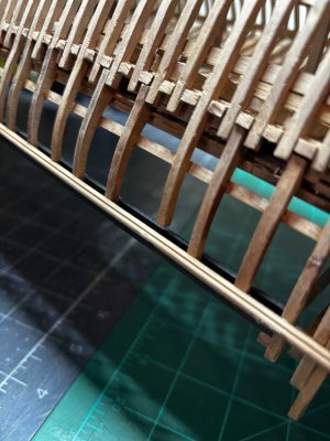
The only thing consistent with my top timbers and standards were their inconsistent heights, very frustrating. It's the kind of situation that can make one question
one's ability to actually follow instructions. Anyway, I think your method should have a decent chance for success even though you know you will have to overcome the kits shortfalls which there will be shortfalls. Later on, down the road when you set the main mast step, there is a significant design flaw in its location relative to one of the vertical deck beam support columns. As an early heads up, I discussed this in my post #375, #377, and #389. You will want to be aware of this one.


IMG_2095.jpeg
 
Later on, down the road when you set the main mast step, there is a significant design flaw in its location relative to one of the vertical deck beam support columns. As an early heads up, I discussed this in my post #375, #377, and #389. You will want to be aware of this one.
Daniel, I remember reading about this in your build log. Thanks for the reminder.
Ken
 
Back
Top