You are using an out of date browser. It may not display this or other websites correctly.
You should upgrade or use an alternative browser.
You should upgrade or use an alternative browser.
I never made a model with lighting, but I guess also this web-page (well known and used by a lot of members) can help youHi all. I have recently brought the occre HMS Bounty and was looking to put LED lights in the open hull. I was wondering if anybody has any information on how to wire them up TIA.
LED Light & Model Building Resources | EvanDesigns.com
Whether you're designing model train layouts, installing mini LED lights, or building the perfect model, our team at Evan Designs is here to help! Learn more here!
Hi I used yellow flickering LEDs to light up my Black Pearl they where purchased from eBay (100 for $10). This was the first time I had used LEDs, I found a site on Google where I could enter the number of LEDs and the voltage I was using and it showed me how to wire them up and what resisters to use. See my Black Pearl log for more details.Hi all. I have recently brought the occre HMS Bounty and was looking to put LED lights in the open hull. I was wondering if anybody has any information on how to wire them up TIA.
Hope this helps Tony
Here we areHi Tony. I can’t seem to find your Black pearl build log.
ZHL Black Pearl 2020 Golden Edition [COMPLETED BUILD]
I hope someone will be interested in another build log of the BP, this will be my second wooden ship model the first was the Rattlesnake by Mamoli nearly 30 years ago. This is the first time that I have attempted a build log so if there is anymore information required please advise. This build...
shipsofscale.com
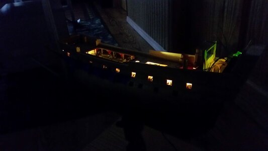
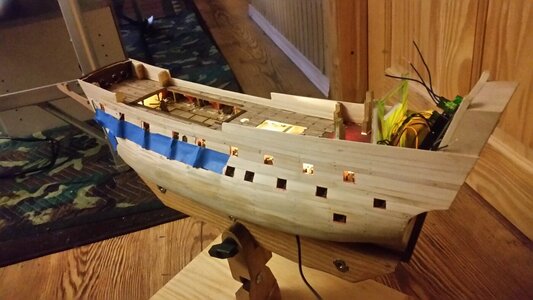
My first model, La Couronne, was lit on two decks with flickering provided by a programmable Arduino UNO card hidden in the stern. The second model is having lighting install on all decks. In this first model, wiring was simply attached on the bottom surface of decks with glue and painted over. On the second model, HMS Sovereign of the Seas, 22 gauge wiring is laid on top of the deck beam support structure, and wires are soldered together to form a parallel circuit of 8 nano LEDS which are aimed downward to the deck below. Hiding the wires is the hard part, and pre-planning where the wiring will go and installing the LEDs as you build is important. You could easily make a part of the ship inaccessible to installing lights if you work too far ahead too quickly. I get all my LED's and the AC/DC converters they run off of from Evan's Designs. They were a great help figuring all this out.
Construction photos of La Couronne
The electronic Arduino UNO card in the stern castle varies voltage between 1.5-1.2V using a program. The program is a text file downloaded to it using a home computer. Once programmed, six separate circuits would flicker the LED's in different random patterns throughout the ship. This is a lot of extra work for a subtle flicker effect. Just lighting without the flicker is good enough for a model, and in retrospect, more accurate given the scale.
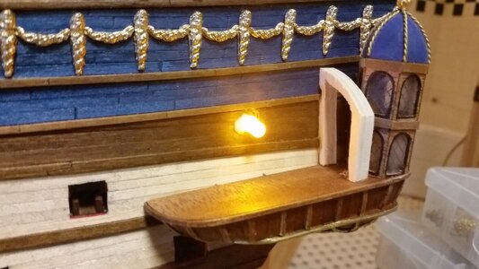
Here is a 5mm yellow LED poking out the side of the hull to illuminate the side gallery, which is to be built over the side of the hull
A 5mm yellow LED was placed in the wooden top dome, aimed downward to create indirect lighting.
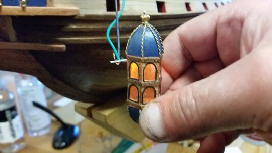
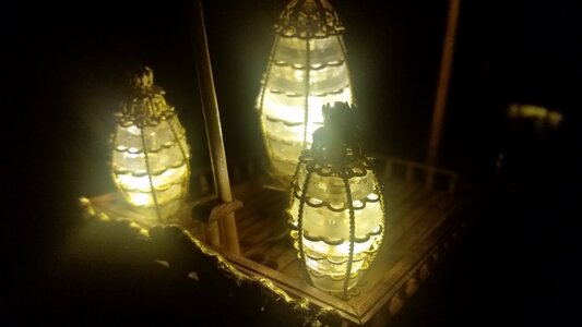
Nano LED's were install in the stern lanterns, two per lantern at different heights.
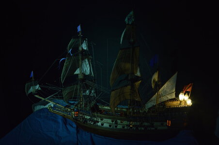
The final effect
HMS Sovereign of the Seas lower gun deck lighting. Two wires, positive and negative, were held to the beams with CA glue and staples made with wire and glued into pre-drilled holes. It was the only way to wire beams that are only 3mm x 3mm. There was not enough wood to cut channels in the beams to hold the wires because the structure was delicate.
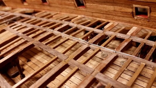
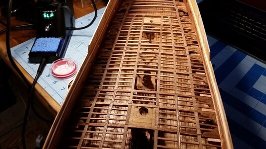
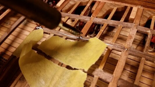
LED's were soldered to the main wires in parallel. Wiring was simply glued to the structure with CA glue. Before that, yellow masking tape held it in place so one could work on soldering.
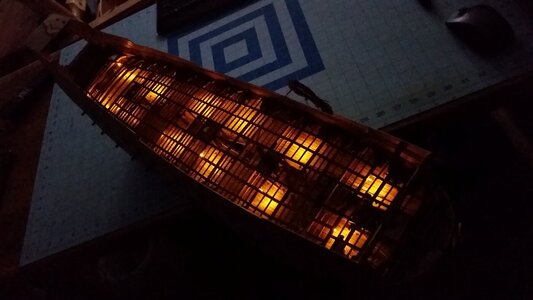
Twelve LED's. The circuit worked!
Thin plywood deck was simply glued onto the support framework, with edges of pieces glued alongside wires instead of on top of them where possible. This is not the bets way to run wiring, and you can come up with several, better planned methods, but it works.
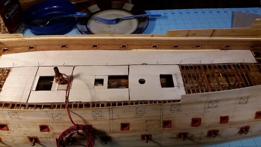
The final result before being covered over with decking
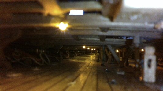
With deck completed overhead

Construction photos of La Couronne

The electronic Arduino UNO card in the stern castle varies voltage between 1.5-1.2V using a program. The program is a text file downloaded to it using a home computer. Once programmed, six separate circuits would flicker the LED's in different random patterns throughout the ship. This is a lot of extra work for a subtle flicker effect. Just lighting without the flicker is good enough for a model, and in retrospect, more accurate given the scale.

Here is a 5mm yellow LED poking out the side of the hull to illuminate the side gallery, which is to be built over the side of the hull

A 5mm yellow LED was placed in the wooden top dome, aimed downward to create indirect lighting.

Nano LED's were install in the stern lanterns, two per lantern at different heights.

The final effect

HMS Sovereign of the Seas lower gun deck lighting. Two wires, positive and negative, were held to the beams with CA glue and staples made with wire and glued into pre-drilled holes. It was the only way to wire beams that are only 3mm x 3mm. There was not enough wood to cut channels in the beams to hold the wires because the structure was delicate.


LED's were soldered to the main wires in parallel. Wiring was simply glued to the structure with CA glue. Before that, yellow masking tape held it in place so one could work on soldering.

Twelve LED's. The circuit worked!

Thin plywood deck was simply glued onto the support framework, with edges of pieces glued alongside wires instead of on top of them where possible. This is not the bets way to run wiring, and you can come up with several, better planned methods, but it works.

The final result before being covered over with decking

With deck completed overhead

How big does the wire have to be to power these LED's? I worked for the telephone company and the relays we used had wire the size of a hair and smaller. I'm thinking you could stretch it along the top of the beam and hold it in place with shellac or PVA. You could just plank over it, I think.
Since you are making a low voltage circuit with very low current, the wires can be smaller than a human hair. However, these are quite delicate in single strand copper. The wire I used above was 22 gauge, because that's what I had on hand, more than large enough, and it was planked over just fine. The trick was arranging the resistors to be in places that would not affect laying the decking over. I placed them alongside the beams and painted them so you can't see them. Of course, you'd have to be an ant crawling on the deck inside the model to see them.How big does the wire have to be to power these LED's? I worked for the telephone company and the relays we used had wire the size of a hair and smaller. I'm thinking you could stretch it along the top of the beam and hold it in place with shellac or PVA. You could just plank over it, I think.
Cheers dude. ( sorry for the delay in my reply )Here we are
ZHL Black Pearl 2020 Golden Edition [COMPLETED BUILD]
I hope someone will be interested in another build log of the BP, this will be my second wooden ship model the first was the Rattlesnake by Mamoli nearly 30 years ago. This is the first time that I have attempted a build log so if there is anymore information required please advise. This build...shipsofscale.com
Quality dude. I’m looking to my bounty with 3mm yellow flickering LED, s . Going to wire in parallel is it possible to use just one resistor for 6 LED ,s or do I have to use a resistor for every LED.My first model, La Couronne, was lit on two decks with flickering provided by a programmable Arduino UNO card hidden in the stern. The second model is having lighting install on all decks. In this first model, wiring was simply attached on the bottom surface of decks with glue and painted over. On the second model, HMS Sovereign of the Seas, 22 gauge wiring is laid on top of the deck beam support structure, and wires are soldered together to form a parallel circuit of 8 nano LEDS which are aimed downward to the deck below. Hiding the wires is the hard part, and pre-planning where the wiring will go and installing the LEDs as you build is important. You could easily make a part of the ship inaccessible to installing lights if you work too far ahead too quickly. I get all my LED's and the AC/DC converters they run off of from Evan's Designs. They were a great help figuring all this out.
Construction photos of La Couronne
View attachment 300890
The electronic Arduino UNO card in the stern castle varies voltage between 1.5-1.2V using a program. The program is a text file downloaded to it using a home computer. Once programmed, six separate circuits would flicker the LED's in different random patterns throughout the ship. This is a lot of extra work for a subtle flicker effect. Just lighting without the flicker is good enough for a model, and in retrospect, more accurate given the scale.
View attachment 300891
Here is a 5mm yellow LED poking out the side of the hull to illuminate the side gallery, which is to be built over the side of the hull
View attachment 300892
A 5mm yellow LED was placed in the wooden top dome, aimed downward to create indirect lighting.
View attachment 300893
Nano LED's were install in the stern lanterns, two per lantern at different heights.
View attachment 300894
The final effect
View attachment 300896
HMS Sovereign of the Seas lower gun deck lighting. Two wires, positive and negative, were held to the beams with CA glue and staples made with wire and glued into pre-drilled holes. It was the only way to wire beams that are only 3mm x 3mm. There was not enough wood to cut channels in the beams to hold the wires because the structure was delicate.
View attachment 300898
View attachment 300899
LED's were soldered to the main wires in parallel. Wiring was simply glued to the structure with CA glue. Before that, yellow masking tape held it in place so one could work on soldering.
View attachment 300900
Twelve LED's. The circuit worked!
View attachment 300901
Thin plywood deck was simply glued onto the support framework, with edges of pieces glued alongside wires instead of on top of them where possible. This is not the bets way to run wiring, and you can come up with several, better planned methods, but it works.
View attachment 300902
The final result before being covered over with decking
View attachment 300907
With deck completed overhead
View attachment 300908
Hello, i will be doing some LED lighting on my two current builds, so if you want you can check it out...Hi all. I have recently brought the occre HMS Bounty and was looking to put LED lights in the open hull. I was wondering if anybody has any information on how to wire them up TIA.
Columbus ships, Santa Maria and Pinta, kit by Amati... [COMPLETED BUILD]
Nothing fancy is happening, today i was working on Santa Maria first planking layer.... Lots of glue, sanding, cutting, fitting... Want to share one very useful tool one of our member was kind to share (thanks lakedaisy) which allows to run very precise line of carpenter' glue. I was always...
shipsofscale.com
It is usually done with one resistor per LED. and Evan's Designs sells 3V nano LED's with resistor already built into one lead wire. Those are what I used, and all the LED's and the AC/CD wall plug and transformer are relatively inexpensive. I believe you can calculate the resistance required to using just one resistor located in the main wire that feeds the circuit. The flickering LED's might flicker too much to create the right effect. That's why I programmed the Arduino UNO card to make the flicker very subtle and random. Still, unless you actually want the obnoxious flicker, it's better to leave the lights steady. It depends on your preference. You can always buy one flickering LED and try it out first before you buy more.Quality dude. I’m looking to my bounty with 3mm yellow flickering LED, s . Going to wire in parallel is it possible to use just one resistor for 6 LED ,s or do I have to use a resistor for every LED.
During my 'Railroad Modelling' days I bought SMLED's (surface mount) with wires ready soldered from China via ebay. Saved a lot of frustration soldering & were cheap at something like £4 for 20. I'm also building Bounty but Billings Boats kit, which needs some kit bashing as some of the plan details are for her origin as a collier, Berthia.Quality dude. I’m looking to my bounty with 3mm yellow flickering LED, s . Going to wire in parallel is it possible to use just one resistor for 6 LED ,s or do I have to use a resistor for every LED.
Enjoyed the thread about installing LEDs. I did that (not as nicely) on a carrier model so one could see some of the hangar deck. LEDs are run by batteries located in an on/off switch box; nothing sophisticated. May consider adding LEDs to a fishing boat model that has lanterns at the bow.
Hi there, I’m a bit sorry a lot of a novice in LED lighting I wired 4 LED,s in parallel with individual resistors but the 4 th one is very dull. By my calculations the LED,s are 1.8 /2.2 volt as described on the packet I’m running them of a 9volt battery so I guess for arguments sake 4x 2 volts is 8 volts is that the reason that the remaining 1volt off the battery is the reason for the dullness. I watched the Evans videos and they run up to 48 LED,s off one 9 volt battery am I doing something wrong.It is usually done with one resistor per LED. and Evan's Designs sells 3V nano LED's with resistor already built into one lead wire. Those are what I used, and all the LED's and the AC/CD wall plug and transformer are relatively inexpensive. I believe you can calculate the resistance required to using just one resistor located in the main wire that feeds the circuit. The flickering LED's might flicker too much to create the right effect. That's why I programmed the Arduino UNO card to make the flicker very subtle and random. Still, unless you actually want the obnoxious flicker, it's better to leave the lights steady. It depends on your preference. You can always buy one flickering LED and try it out first before you buy more.


