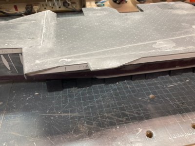
Mini Hobby 80502 1/350 Scale USS Enterprise CVN-65 Early

Joined
May 8, 2021
Messages
36
Points
48

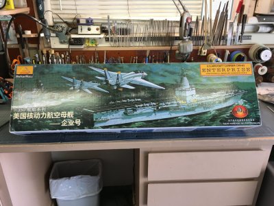
Kit Box (1).JPG

The kit on my workbench

Part 1

The first USS Enterprise was a 70 ton sloop armed with 4 twelve pound cannon captured from the British in 1775 on Lake Champlain. She was burned in 1777 to prevent recapture. The second Enterprise was a originally a private 8 gun schooner built in Maryland that served on Chesapeake Bay and around Maryland during the same time. The third Enterprise was a 135 ton, 85 foot schooner armed with 6 twelve pounders. She served with the Navy from 1799 to 1823 when she ran aground and was lost. During her career she fought in the undeclared war with France from 1799 to 1801 and in the Mediterranean during the Barbary Coast Pirate Wars. She was rebuilt and up gunned to 16 twelve pounders fighting in the war of 1812 when she captured the British brig Boxer. The fourth Enterprise was a schooner of 194 tons armed with ten guns built at the New York Navy Yard. She entered service in 1831 and served in the Atlantic, Pacific and the East India Station. She was sold in 1845. The fifth Enterprise was a wooden steam powered Corvette displacing 1375 tons and was nearly 200 feet long. She was armed with 10 guns and crewed by 184 men. She operated in the Atlantic, Mediterranean and the West Indies. She would become a training ship and was sold in 1909. The sixth Enterprise was a private yacht converted to a Motor Patrol Boat for service in World War I. She was purchased in 1916 and sold in 1919.

The first six ships named Enterprise served proudly but the seventh, CV-6 made a memorable name for herself during WWII. She was built in the late 1930’s at the Newport News Shipbuilding and Dry Dock Company. The keel was laid in July, 1934 and she was launched on October 3, 1936. She was commissioned in 1938 and was the second ship of the Yorktown class, 1 of 3 purpose built aircraft carriers. The Navy’s first. Of the three, only Enterprise would survive WW II. At one point she was the only aircraft carrier in the Pacific. She was the first vessel to sink an enemy combat ship, the submarine I-70. She fought in every major battle in the Pacific and was the most decorated ship in US Naval History receiving 19 battle stars. She was the only ship to receive both the Presidential and Navy Unit Citations. The Japanese called her the Blue Ghost after reporting sinking her several times. Of all the ships built during the war she truly deserved to be set aside as a monument or museum. Tragically she was sold for scrap in 1958 despite the efforts to preserve her. Six portholes from the bridge of CV-6 were removed and used on the Captain’s cabin on CVAN-65. These are to be moved to CVN-80 which will next bear the name of Enterprise.

The keel of USS Enterprise CVAN-65 was also laid down at Newport News Shipbuilding and Dry Dock Company on February 4, 1958. She was launched on September 24, 1960 and was commissioned into the US Navy on November 25, 1961. She first put to sea as a commissioned vessel in January of 1962. In 1975 she was re-designated as a CVN and would remain so for the rest of her service. In 2012 she would complete her final deployment, decommission and be consigned for scrapping. During that 51 year period she would deploy overseas 25 times. After her first overseas deployment she returned to homeport only to put to sea again for the Cuban Missile Crisis. She made 6 combat deployments to Vietnam between 1965 and 1972. During the 1975 deployment she participated in the evacuation of Saigon. Over the course of the War on Terrorism she participated in every major action except Desert Shield/Storm because of a yard period. She served on the East coast, moved to the West coast and returned to the East. 23 Captains commanded her. Over the course of her career she was awarded 19 medals and ribbons, many awarded multiple times. She was the first nuclear powered aircraft carrier and the 8th ship of the U.S. Navy to bear the name Enterprise.

CVAN-65 was 1,123 feet long overall, 1,040 feet at the waterline. Her maximum width is 257 feet with a beam of 133 feet at the waterline. From her keel to the top of the mast she was 269 feet in her 1978 configuration. She was so tall that the UHF mast extension was designed to fold over to get under the Golden Gate and Bay Bridges. She displaced 90,000 tons fully loaded. Various armament configurations were tried over her career but because of budget limitations Enterprise was armed with only her air wing for defense as launched. She went down in history as the first nuclear powered aircraft carrier.

In February, 1958 I was not quite 3 years old. The keel laying made no impression on me. I might have heard her name on the news a time or two as I grew up. In 1969 I watched the news reports in horror while she burned. In 1972 I was in my junior year of high school, a C & D student. A level of scholarship attained more from not trying than any fault of the school, curriculum or the teachers. I had no interest in going to college and generally disliked school. I’d had a part time job since I was 13 so I had no aversion to work just the classroom. I spent most of my free time building model airplanes and day dreaming about flying. When I wasn’t doing that I was riding or working on my motorcycle. I never took the SAT or the ACT college placement tests, I barely did homework. In December of 1972 the draft lottery was held and I watched it with my best friend. This lottery was for men born in 1955 who would be of age (18) in 1973 (Me). They drew my birthday early, I believe as number 44! It turned out that this would be the last year of the draft. The1973 lottery was held but never filled. The All Volunteer Military arrived a year too late for me. My friend was destined for college. Knowing that there was no deferment in my future, I decided to make the rounds of the Armed Forces Recruiters. Better to enlist and get some choice was my thinking at the time. I went with the Navy.

The Navy recruiter in my hometown of Findlay, Ohio was a Chief Aviation Electronics Technician named Don La Favour (I hope I spelled that right Don). He was primarily in patrol aircraft. He had served as aircrew and he was matter of fact, and I felt, honest. After testing me he said that I could virtually ask for any enlisted program and get it. Apparently I had learned something after all. He offered me a six year active duty nuclear power program and then a similar advanced avionics program. I only wanted to serve the minimum and then get out. I told him that all I wanted to do was work on airplanes. He seemed to understand that. I had worn glasses since the fourth grade, so I thought that I probably wouldn’t qualify for any flight program. Working on planes was better than nothing. (I could have gone aircrew after all but when I was rated an Aviation Fire Control Technician there were no flying billets available for my rate.) Chief La Favour was able to guarantee a school seat in 1 of 4 aviation electronics ratings providing I could pass the schools, AT, Aviation Electronics Technician AQ, Aviation Fire Control Technician, AX, Aviation Antisubmarine Warfare Technician or TD, Tradevman or more correctly Training Device Man (More school yay!) So I enlisted in the Navy for a standard 4 year enlistment. (4 years active and 2 more in the reserves, the least amount I could serve for and still get my guaranteed school seat.

He also got me a delayed entry which let me enjoy a final summer vacation with my friends. On September 22, 1973 I arrived at Great Lakes Naval Training Center at 0200 as a Seaman Recruit and began a 22 year career with the Navy. I surely did not know that I would stay that long at the time. I got my draft call-up in October while still in boot camp. They do start out “Greetings…” I took the letter to my Company Commander and asked him what I should do. His answer was to have me drop and give him 50, He said, “The draft can’t have your a_ _ because your a_ _ belongs to the Navy!” By the end of boot camp I knew that I did not want to be a TD because they were virtually on permanent shore duty and they worked on trainers not aircraft. So of course I was designated a TD out of Boot Camp.

From December of 1973 to June of 1975 I went to various Navy Schools. For a guy that hated school it seemed endless. But it was an eye opener too seeing how math and physics all worked together to become electronics and it all slowly was made clear and even interesting to me. The Navy also provided a little better motivational tools than the public schools did, at least in my case. Pass or get stuck in some s_ _ _ job. While I was attending Avionics “A” School I happened to ask if there was a way to change rates during class. Turns out one of my classmates who was designated an AQ, wanted to be a TD because it was his father’s rate. By virtue of a pair of Special Request Chits, the Navy’s version of you can ask for anything and maybe you’ll get it forms, we were able to exchange positions.

In 1974 or 75 the Navy began airing a new batch of television recruiting commercials while I neared the end of my schooling. One of them stands out to this day, Drum roll, “Dawn, the South China Sea, flight deck of the USS Enterprise. You are there.” Some scenes of aircraft on the flight deck and it finished up with “Join the Navy it’s not just a job, it’s an adventure!” I was on my way.

In February of 1975 I reported to NAS Lemoore, California for training at VA 122 (Attack Squadron or ATKRON 122) (again more school). I arrived obligated for 6 years of active duty as a Third Class Petty officer. Something I signed up for while in Tennessee. But this time I was learning my trade and it was a hands-on type of school. I would be part of the Integrated Weapons Team (IWT) for the LTV (Ling, Tempco, Vought) A-7E Corsair II. I learned about the RADAR, Inertial Navigation System, the Tactical Computer, Weapons Delivery, Heads Up Display and a plethora of other equipment. It was actual work on the airplane. While there, two of my classmates and I were told to be prepared to travel immediately overseas. This was during the evacuation of Saigon. We remained on standby for a couple of weeks. In the end we finished our school normally. In June of 1975 I finally checked aboard VA-27. My first fleet unit, the “Royal Maces, were assigned to CVW-14 (Carrier Air Wing 14) which deployed aboard the aircraft carrier USS Enterprise! In January of 1976 the Air Wing went aboard Enterprise for the first time in the deployment cycle as she began REFTRA, (Refresher Training,) this was my first time at sea.

I spent a total of six years with VA-27, two back-to-back sea tours. I made two sets of work-ups and two full deployments to the Western Pacific and Indian Ocean, (WESTPAC/IO) aboard the “Big E” and another deployment aboard the USS Coral Sea CV-43. It turns out that I was good at electronic repair and troubleshooting. I liked what I was doing and so I had stumbled into a job that was my niche in the world, it caught my interest. I became a part of something bigger than just me, a valued member of a team. I found that working on jets on the flight deck was an adventure all right. I saw the world. I saw a bunch of water horizon to horizon too. The stars at night are something to behold at sea. I have a good collection of “Sea Stories that I love to trot out upon meeting (drinking) with other old salts. Most have some element of truth to them. Not long after I left VA-27 I was advanced to First Class Petty Officer.
FB_IMG_1660571209944.jpg

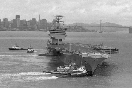
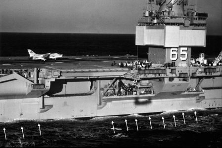
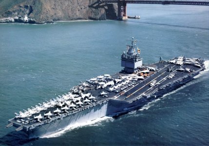
Enterprise outward bound from Alameda in 1978

I wanted a model of my first ship as she looked during the 1978 deployment with a full air wing, a time rich in memories for me. This was the ship’s final deployment with the beehive island and my second. I originally set out to build the 1/400 scale Aurora/Monogram/Revell, (A/M/R) kit of the Big E. (They even sold the Aurora version in the Enterprise ship’s store.) In 1992 a friend gave me his Aurora kit which he had started on. Later I found a Monogram version with a more modern air wing and I obtained one Arii aircraft set. I started on it in 2006 this was almost 20 years after I got the Aurora kit. I got a good way into building up a hanger bay for that kit. I had several errors corrected too.

As I labored over the hanger bay I kept finding new photos of the ship almost as soon as I scratch built a part which then required a rework of what I had just done. I quit trying to proceed on memory for everything. I made a good set of drawings to pin down details after scouring the internet for photos. The drawings were based on the 1/400 scale model. First I drew the hanger bay and then the exterior and finally some of the aircraft. I still fiddle with those drawings making corrections. Despite my best efforts I was unable to get any more aircraft sets. The only available one was the Otaki/Arii aircraft set which while not great had all the right types of planes except for the EA-3B Skywarriors. Shapeways sold several aircraft in that scale, but they were expensive and not all that good for the money. I could not find more of the Arii sets or if I did the seller wanted a prohibitive amount of money. With everything I had it wasn’t even half of the full air wing.
Rough Construction 073.jpg

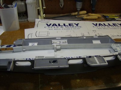
Work in progress on the hanger on the Monogram kit. I worked in a motorcycle shop at the time the and some of the plastic came from license plate inserts that I kept when the store changed it's name.

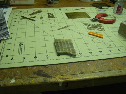
There were very few aftermarket parts available in 1/400 scale. There wasn’t even a purpose made set of photoetch. I learned how to make my own photoetch starting with the grated elevators. But this is very messy and labor intensive. Because of that and a warped and twisted hull that wouldn’t stay straight, (despite boiling water and clamping to a flat surface). I finally relegated it to the shelf of doom. I purchased the Arii kit of the early Enterprise but while it has better detail than the Monogram version, disappointingly it isn’t as accurate dimensionally. So I decided to get a 1/350 scale model having seen the Tamiya kit built up in many online posts and magazine articles. It looked very good although most of the builder’s spoke of errors they didn’t specify exactly what. There are a bunch of aftermarket items including additional aircraft in 1/350 scale. You can even buy a 3D printed hanger bay if you can afford it.
Elevators 053.jpg

Elevator 4 from the Monogram kit with my photoetch grate.

Tamiya released their kit of the USS Enterprise CVN-65 in1984. Trumpeter produced what most sources say was a copy of the Tamiya kit in the 1990’s and then in 2001, Mini Hobby got the molds and brought out two versions of the kit, number 80501, Modern and 80502, Early. I found a source in China on eBay and purchased an “Early” version and waited nearly 6 months to get it because of the COVID pandemic. The early version turned out to be the same as the modern with the exception of 2 parts to represent the early beehive island. And those are not accurate. All the sponsons for the modern version are also present on the early version kit, CIWS mounts, MK-29 missile launchers, life raft canisters, antennas and the mast are in both kits. None of which is correct for the ship before 1980. There aren’t any alternate parts trees to truly represent the early version. The one advantage of the Mini Hobby kits is that they are significantly cheaper than the Tamiya. Mine was less than $50.00 and no shipping.
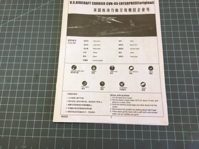
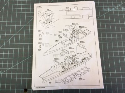
Booklet (1).JPG

The instruction booklet

Booklet (5).JPG

The motorization addendum

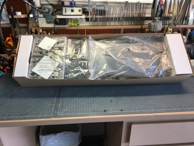
Kit Box (2).JPG

The parts in the box

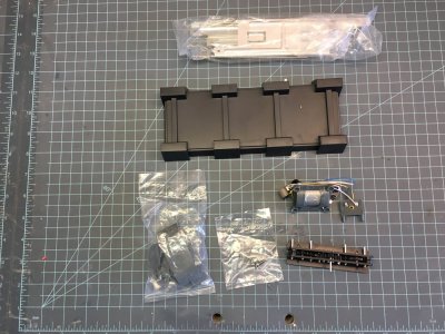
Motorization, Stand and Metal Hull Reinforcements.JPG

Motor, battery box, transmission, metal parts and stand
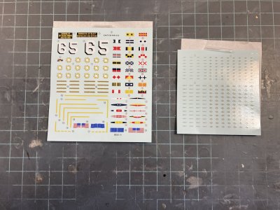
Decal Sheet 01.JPG

The decal sheets the color is a bit too blue and the deck hatch decals should be a white center surrounded by a red and yellow band. The Tamiya sheet is the same but the blue color is more correct.
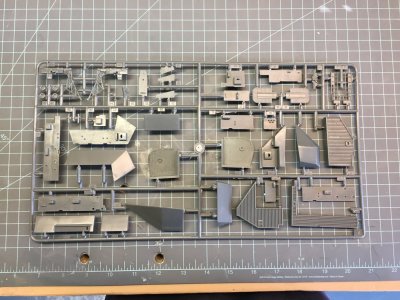
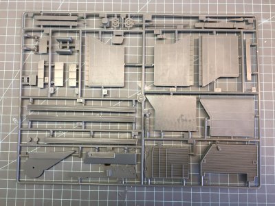
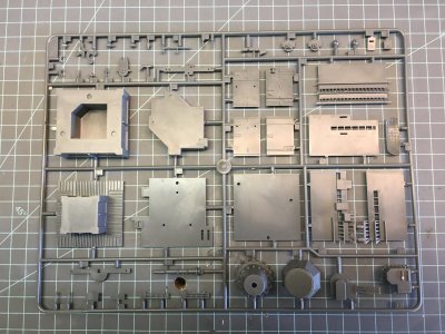
Sprue A (2).JPG
Sprue A

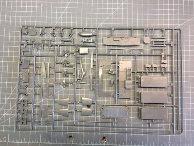
Sprue B (1).JPG
Sprue B

Sprue C (2).JPG

Sprue C

Sprue D (1).JPG

Sprue D. Note the beehive parts, those are the only things in the kit to represent the early version of the Enterprise.
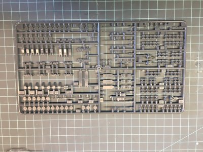
Sprue E (2) X 2.JPG

Sprue E (X 2)

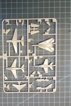
Sprue P (2) X 8.JPG

Sprue P (X 8) If you compare this to the Tamiya aircraft set number 1 you will see they are the same.
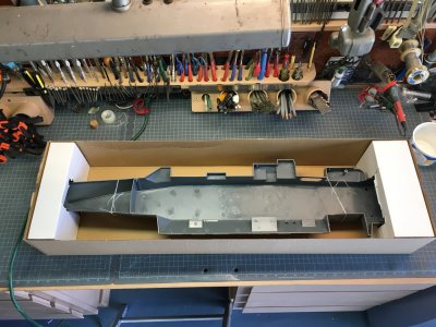
Kit Box (4).JPG

The Hull in the box (note that it is fitted together)
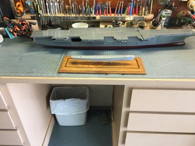
1-350 Enterprise Hull Compared to 1-350 Fletcher Hull.JPG

Hull and flight deck components compared to the 1/350 scale Fletcher class destroyer

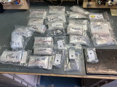
In the box you will find 6 sprues of ship parts, 8 of aircraft, 3 sections of flight deck, a 3 piece hull which is fitted and screwed together but not glued up, 2 sections of stand, a bag of motorization parts and some metal braces and screws. There is a small sheet of decals for the ship and another for the aircraft. Essentially the same stuff with minor differences compared to the Tamiya kit. There is a 20 page, 7 3/8 x 10 ¼) black and white instruction booklet and an additional addendum sheet showing assembly of the motorization components. I watched a You Tube series by Ken Chee Kum , (Modelar)and he says that these motors are often in Mini Hobby Kits. Watching his build brought out a lot of the issues I would face. He used the Eduard photo etch in his build. I find that watching others building models to be very helpful. You can pick up great techniques and have a better idea of the pitfalls. The ship parts are in medium grey plastic except the lower hull which is appropriately in red, while the aircraft are light grey and the stand is black. The sprues are all bagged but not separately, 2 or more are bagged together. And all the aircraft are in one bag. The model is boxed in a sturdy cardboard tray but this is annoyingly slid into an end opening cardboard box. As soon as I started working on the model I modified the box so it could be opened from the top.

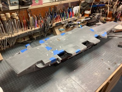
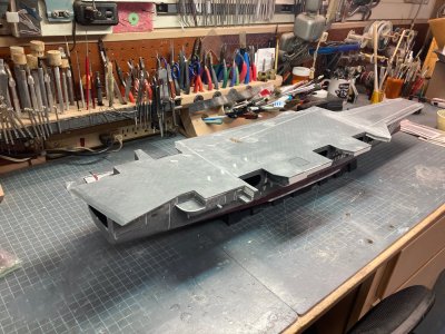
My first impression was this is the Tamiya kit. But the detail is on the soft side. None of the sponsons have the cut outs for the elevator supports to pass through. The A/M/R version has these. The upper hull is the same as Tamiya’s in the front and back sections but then it is further divided at the waterline. The Mini Hobby box is long enough to hold the full hull so they could have made the hull without the separate bow especially since the waterline section is a single piece. The flight deck is broken into 3 sections so you can access the batteries in the hull after you motorize it. I vaguely remember the Tamiya kit could be motorized also when it was first released. The beehive island part was reported to be oval rather than round in a review I read, but measuring with a digital caliper shows the parts to be the same in X - Y dimensions. The upper beehive should have 6 rows of Alford T type receiving dipole antennas. Four rows are exposed, some 240 little T’s. Thankfully the upper 2 rows were so fragile they were encased in a protective tube. The kit does not have anything to represent these. Their flight deck breaks down the same way as the Tamiya kit’s, even the metal brackets are similar. The switch for the motor would stick up through the flight deck midsection though! I can’t find any indication of this in any Tamiya builds. The decals for the ship appear to be too light in the blue areas.

I had picked up a Tamiya instruction booklet and a decal sheet from eBay and compared the two kits based on instruction guides. The sprues are lettered the same but they are not laid out identically. The part numbers are not the same. The Tamiya kit appears to have elevator 1 molded with the flight deck and you add the support structure to the underside. The remaining 3 are assembled from 3 parts. All the Mini Hobby elevators are molded separately, but only elevator 1 has a separate underside support structure. The remaining elevators assemble from 2 parts. The aircraft sprues will allow you to build 40 aircraft total but there will be 8 A-7E and 8 F/A-18A or C aircraft. No air wing included both types it was one or the other. Like the Tamiya kit there are no E-2B/C, SH-3D/H or EA-6B’s. Tamiya does make a second aircraft set to cover these planes and also adds F-4C Phantoms. F-4’s were replaced in most air wings by the F-14A’s again one or the other type. F-14’s couldn’t fly from Midway Class or earlier carriers.

I had purchased a set of scale drawings from the Floating Dry Dock in 1/192 scale while working on the Monogram model which were reduced to 1/400 and upped later to 1/350 scale. These were useful in getting my drawings right. The owner helped me a great deal with this he is a modeler as well as an entrepreneur. The plans are from his G series which is made up from USN Booklets of General Plans. These appear to be builder’s proposal drawings not the final product. Curiously the island has Pri-Fly (Primary Flight Control) on the same level as the Navigation Bridge a mistake also present on the A/M/R model. It was always on the level above the Navigation Bridge. Also drawn is a sponson forward of elevator 1 at the hanger deck level which was present on the just launched ship but then later was removed. I could not find any information about this. I do have a photo. The drawings matched the Monogram kit almost exactly but they were off for the Tamiya Kit (and the Arii.) The waterline dimensions were almost right on the money, but the length and width of the flight deck is too big. Maximum width of the flight deck, including catwalks is 257 ft. according to Bert Kinzey’s book. In 1/350 scale that would be 8.811 Inches. Mini Hobby’s measures 9.375 (9 3/8) inches at the widest point, 273 scale feet. The length is a bit long by about .25 inch. The three starboard elevators are out of position by .25 inch too far aft each. I believe these dimensional faults are present on the Tamiya kit also. I do not have any plans to fix these problems. I wasn’t willing to cut up the Arii model to fix similar errors either. The corrections would require a massive amount of work. Tape it all up and it looks like the Enterprise.
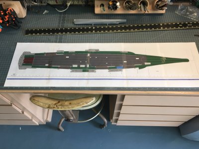
1st Deck Drawing.JPG

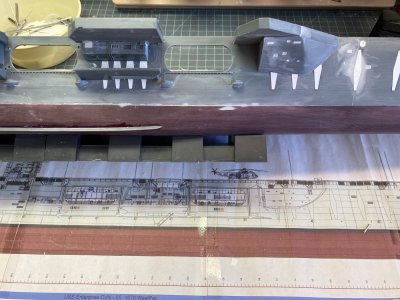
One of the many drawings I made this is the 1st deck drawing of the hanger bay

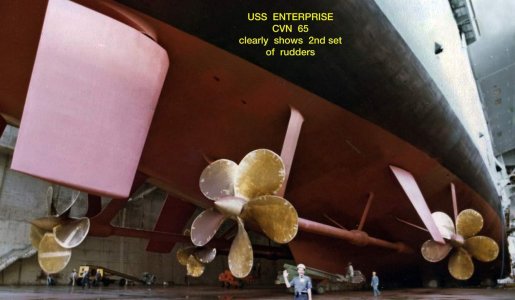
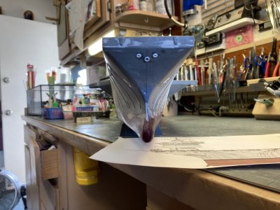
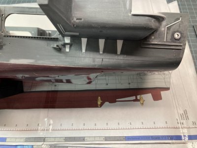
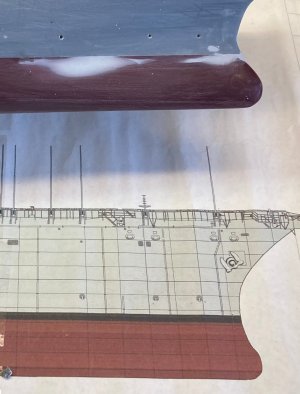
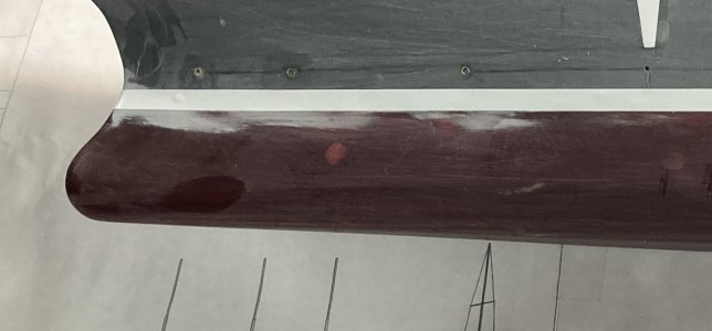
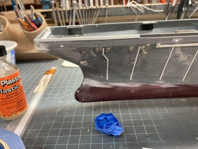
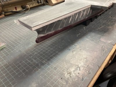
The larger flight deck should make it easier to place the whole air wing aboard. The real ship had problems with this for many years especially with the “Grumman Air Wings” of 70’s and 80’s. I intend to build the kit full hull but there is an error with the lower hull that I am thinking about correcting. The keel extends down the centerline aft and comes to a wide blunt end. This is wrong it should end in a tapered blade like shape. The Tamiya and Arii model also have the same problem. I’m not sure why this is wrong on so many kits. The A/M/R hull was more correct. With the full hull on display the error will be visible. Probably no one looking at it would know the difference but the full hull would look more graceful corrected. I do intend to add a full hanger bay. I purchased sheets large enough to cut out the whole thing from Evergreen Plastic.
 
Last edited:
I love the fact it has a one piece hull..Thumbsup:)Thumbsup
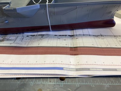
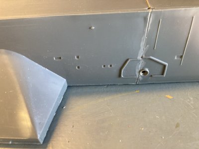
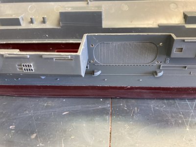
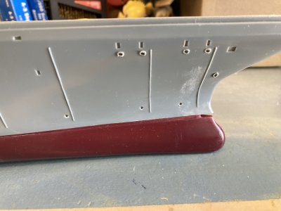
It is actually a 3 piece hull. Like the Tamiya kit it has a separate bow in the same spot which is screwed in place. But it also has a full waterline which is a single piece. You can see here where the forward hull is screwed to the aft. The twist tie covers the seam. also you can see the guide for attaching the forward missile sponson added to the ship after 1978. On the port side is the guide for the CIWS sponson also not added till after 1978. I will have to glue the bow on and remove and fill the screw holes. All the guidelines for new sponsons will have to be removed.


Accuracy (11).JPG

08-dcs09_207_1.jpg

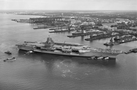
The just launched Enterprise on the way to the fitting out dock. Look just forward of the lowered elevator 1 there is a sponson there. When Enterprise went out for sea trials this sponson was gone.

Sponson 1.jpg

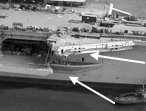
This cropped version is a little clearer. The upper arrow points to the missing bulge under the point area of the flight deck. I posted these photos on an Enterprise Facebook page asking any plank owners if they knew what happened here. None of my books document it.
 
Last edited:
I grew up in San Francisco and often saw the Enterprise come and go under the Golden Gate Bridge. Very impressive! UNTIL......

In April 1983, the USS Enterprise (CVN-65) ran aground on a sandbar in San Francisco Bay while returning from deployment, remaining stuck for several hours, and coincidentally, George Takei, who played Mr. Sulu on "Star Trek", was aboard as a guest of the Navy.

Here's a more detailed account:

  • The Incident: The USS Enterprise, a nuclear-powered aircraft carrier, ran aground on a sandbar in San Francisco Bay.
  • Time and Location: The incident occurred in April 1983, while the ship was returning from a deployment.
  • Coincidence: George Takei, who played Mr. Sulu, the helmsman of the fictional starship Enterprise in "Star Trek," was on board as a guest of the Navy at the time.
  • Media Coverage: The event received significant media attention.
  • 3,000 friends and family members were awaiting the crew's arrival on shore
  • The ship was stuck for several hours
  • The ship was only 1,000 yards from shore
  • Two admirals were on board to mark the occasion
Notice the crew acting as a counter weight to help free the keel.
Posted as a fun fact only. Enjoy the build.:)


Enterprise Grounding.jpg
 
I remember hearing about the story. I was on shore duty at NAS Lemoore at the time. The incident was very embarrassing for the Navy. Thankfull nothing like that ever happened to me. I can imagine the frustration of the crew and the waiting family after being separated for the length of a deployment only to have to wait some more at the end.
 
We ran aground on Bishop's Rock in November 1985 during workups. Tore a 150 foot gash in the hull. It was unpleasant.
 
Part 2

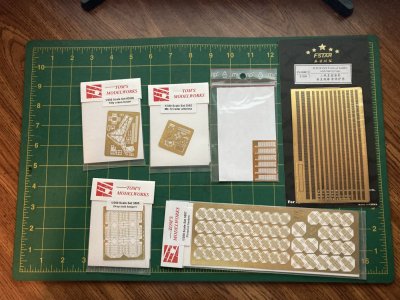
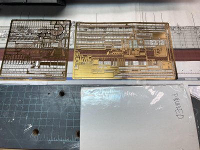
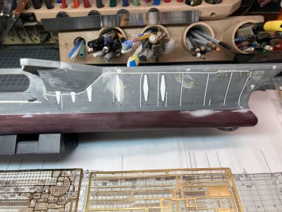
Once I had purchased the model I started buying aftermarket stuff and references over a period of several years. I waited for sales and price reductions on hobby shop websites, eBay and Amazon. I corresponded with sellers who helped me out. There are three manufacturers currently producing dedicated sets of photoetch for the Enterprise in 1/350 scale, Eduard, Gold Medal Models and White Ensign. The three sets are similar in what each furnishes but there are differences. Tom’s Modelworks makes several sets which can be used to add detail that is not included in any of the three but they do not have a single dedicated set. Do be aware that all of the three sets for Enterprise cover the model after 1980. Nobody makes a set specifically for the ship prior to that. I actually purchased a lot of photoetch but I wouldn’t go overboard like that if I had to buy photoetch now as the prices seem to have risen a great deal since I bought mine.

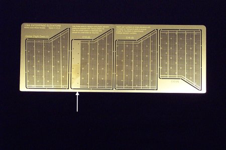
I brought the Gold Medal Sets first. The owner retired recently and shut his website down but he made an agreement with Squadron.com and they carry the full line https://squadron.com/ . They are the only company providing a set featuring the grated elevators. But this has the plating added in 1980 to elevator 2 to stiffen it up (GMM-350-2A). Unfortunately this is not correct for 1979 or earlier. All four elevators were fully grated from 1961 to 1979. In order to get a fully grated elevator number 2 you would need a second set (elevator 3 can be flipped over and it is a match but the tie down points won’t line up with the flight deck. You could also attempt to correct the etching. I am going to try this. It was somewhat disconcerting to walk across one of these elevators underway and see the water fly by below you. If you are building a model from around 2001 to 2012 you won’t need these as all the elevators appear to be plated over. Check your references I found pictures in the 1996 and 1998 Cruise books showing grated elevators and then in 2001 they appear to be plated over. But I never found a clear shot so that I couldn’t swear to that.

GMM CVN 65 Elevators GM350-2A Arrow.jpg

The GMM-350-2A sheet, the arrow points to the area that should be grated prior to 1979

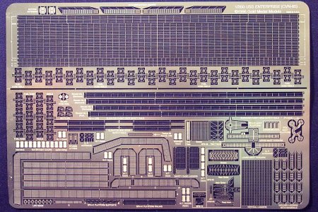
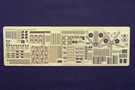
Gold Medal also produces a dedicated set of photoetch for the ship (GMM-350-2) and another for air wing details (GMM-350-30). The ship set contains many parts to detail the island, mast, catwalks and sponsons. There are some parts, bicycles and Stoke’s litters that are not found in other sets. (Actually Eduard set 3 has one litter for the island.) Both sets are thicker than the other companies. The air wing set is nice because it provides parts for the aircraft included in the Mini Hobby/Tamiya kit and also for the second Tamiya aircraft set. The air wing set was designed to work with the Trumpeter Nimitz and Kitty Hawk class models but it is good for any late 70’s to 90’s air wing. To build a whole air wing you would need several of these and you would then have many left over parts. I was able to buy both in a combination set for a lower price. I don’t know if they are available this way now.

GMM CVN65 GMM 350-2.jpg

GMM-350-2

GMM CVN65 Airwing GM350-30.jpg

GMM-350-30

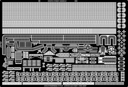
I then bought a White Ensign set this has the usual detail up parts similar to the others https://www.whiteensignmodels.com/ . It has several combined ladder/catwalk parts that are only available elsewhere in the Eduard 5 set. These ladders are from the catwalks to the 03 level and have the attached landing at the bottom with handrails. And it is the only set with the counter balanced rotating handles for the whip antennas.

WEM 3522.jpg


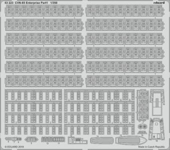
Eduard has the most extensive set(s) https://www.eduard.com/ . They make 5 sheets which can be purchased separately or you can buy 3 in one “Big Ed” set and the final 2 in a second. The second set also includes a sheet of figures. If you buy the Big Ed sets the price is cheaper than buying the 5 sheets separately. I purchased all but Set 1 (P/N 53223). This set is primarily parts to detail all the life raft canisters on the 1981 to 2012 ship. It also includes detail parts for the ships boats in the kit. Except for the boats, the parts do not apply to the older ship.

Part 1 53223.jpg

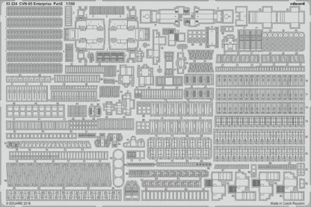
Set 2 (P/N 53224) is dedicated to the supplied aircraft and flight deck equipment. It details the kit NS-50/60 Tilly, but doesn’t have a brass gantry for it, supplies 4NC-2 electrical power carts and details the MD-3 tractors, builds up 2 new MBD-5 fire engines and 2 NAN-3 nitrogen carts. There are tow bars and parts for the aircraft in the kit.

Part 2  53224.jpg

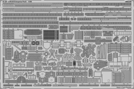
Set 3 (P/N 53227) concerns details for the Island and mast. Some of these won’t apply to the older ship but can be modified to fill other purposes. It has a part to add the Flight Deck Officer’s port side view window which no other set provides. It sticks out from the port side of the island at the flight deck level and affords a forward and aft view of flight deck operations. It appears to always have been there. None of the model kits feature it in the plastic parts.

Part 3 53227.jpg

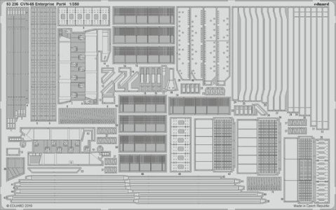
Set 4 (P/N 53236) covers deck edge elevators and 3 of the 4 JBD’s, (Jet Blast Deflectors). Cat 4’s JBD is not provided. The parts for the underside of the elevators are not available in other etch sets. Parts are provided to detail the flight deck if elevators 2 and 3 are lowered.

Part 4 53236.jpg

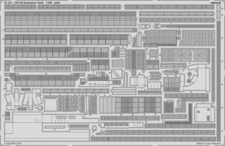
Set 5 (P/N 53237) is for the lower hull, flight deck safety nets and sponsons. Mesh grills for all the vents and intakes on the hull sides. One thing I noticed while studying the instructions is that Set 3 has you remove a catwalk area between elevators 2 and 3 but the parts to replace them are in Set 5.

Part 5 53237.jpg

Tom’s Modelworks has some nice sets which I bought for the Tilly gantry, drop tank racks in the hanger overhead, life raft baskets for the older ship and more caged ladders https://www.tomsmodelworks.com/catalog/index.php . I also got their aircraft frets for the planes in the air wing. Each sheet will detail up six aircraft and includes some interior detail. I also purchased generic sets for watertight doors, railings, hose reels and ladders of various types.

Extra (1).JPG

Since all my drawings were based on the A/M/R model they could not be used to cut out a hanger deck for the Mini Hobby kit. The interior of the two hulls is not the same. I heard of a source on a modeling forum and I got in contact with Tom Pope who had made a set of drawings of the model expressly for building the hanger on the Tamiya kit. He has made a set of scale drawings that will allow you to cut a hanger deck and drop it in. He also includes drawings for the hanger bay bulkheads which will let you build a nicely detailed hanger bay. I am in the process of integrating my drawings with his. https://reviews.ipmsusa.org/review/cvn-65-uss-enterprise-hangar-deck-scale-drawings . There is a link in the article to contact Tom.

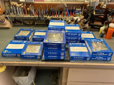
Modelar showed how much better the Trumpeter aircraft are compared to the Tamiya in his videos. I decided to get their aircraft for the flight deck at least. You can buy these in sets of 6 and they cover the air wing on Enterprise in 1978. 24 F-14A’s, 24 A-7E’s, 11 A-6E’s , 4 KA-6D’s, 4 E-2B’s, 3 RA-5C’s, 4 EA-6B’s, 10 S-3A’S, 1 US-3A and 8 SH-3D. There was a total of 93 aircraft in the air wing. To ease deck load we would leave an aircraft detachment behind at NAS Cubi Point, Republic of the Philippines for the duration of the deployment. The amount and aircraft types could vary. It was prime duty to be on the Beach Det. I got on one once for a month ashore. We slept in the barracks, had maid and laundry service and ate in the award winning galley. There was off base liberty every night unless you had a watch. In addition to the air wing we had a detachment of EA-3B’s, (2 A/C) and it was pretty common to see a C-2A Greyhound on deck. Looking over the parts in the Trumpeter kits versus the Tamiya they are superior. So I purchased enough of the Trumpeter aircraft to make up the air wing. During this time frame you would also see SH-2F’s, CH-46’s and CH-53’s. These aircraft could fly aboard from other ships. The SH-2 was the helicopter used most often on Frigates, Destroyers and Cruisers. During UNREP (Underway Replenishment) the other workhorse helicopters could be on deck.

Extra (4).JPG

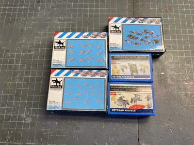
There aren’t nearly enough tractors and other types of Ground Support Equipment in the kit to make a reasonable display. Black Dog makes 1/350 MD-3 Tractors, A/S-32 Spotting Dollies and NC-2 Aircraft Power Trucks that are very nice. https://blackdog-model.com/kategorie/afv/ . Veteran Models makes several sets which will be useful including various RADARs and bridge equipment. I never found a website for these guys but many on line hobby shops carry their products. From L’Arsenal I got chocks, towbars, bitts, fairleads and cargo https://www.larsenal.com/?PGFLngID=1 . I believe they now offer a complete hanger bay. Shapeways provided 40 foot containers to make the ECM Vans, elevator guides, conflagration stations, liberty boats, drop tanks and missiles. From Black Cat Models I got fire hoses, reels, valves and hand wheels. https://blackcatmodels.eu/en/ . There are a lot of things that I didn’t mention here but will cover as I build.

Extra (5).JPG

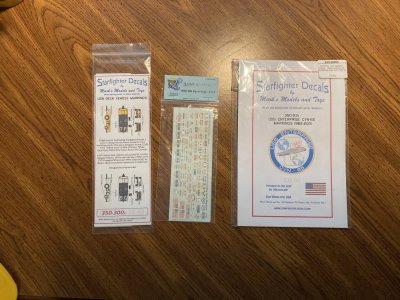
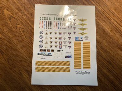
I got a couple of Starfighter decal sheets, 350-53 USS Enterprise Markings and 350-300 USN Carrier Deck Tractor Markings. I also picked up a Flyhawk D3519 USN Signal Flags, Small. From David’s Scale Models I purchased his 1/350 USS Enterprise Hanger Bay Decal Sheet.

Decals (2).JPG

Decals (1).JPG

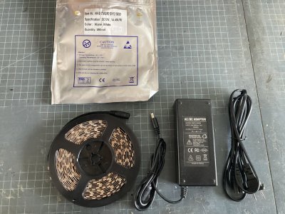
Micro Mark has a Strip LED set for lighting models. It includes a power supply and I will use that to run both the lights and the motor if I can make it work right. https://micromark.com/ . Their LEDs come in the cool white that you normally see along with many other colors. They have a warmer white light that looks more like incandescent light. The hanger bay in my time had this type of light bulbs. At sea out past Hawaii it was more common to have red lights at night but to view the hanger I won’t use the red lights. I have some pico sized individual LED’s for the bridge and the fantail.

IMG_0051.JPG

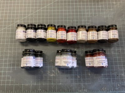
With the demise of Testors Model Master Enamel paints (14.7ml or ½ ounce size) I searched all over for a replacement supplier. (You can still get the small ¼ ounce jars but they don’t match all the military colors.) I do not care for acrylics for base coats. I have tried a few and have had some poor results. Probably my own fault but I have not had these problems with enamels. I do use them for washes and other effects. Humbrol and Revell come to mind but neither of these is widely available in my area of the United States and the prices are ridiculous at $10.00 or more per 14 ml tinlet! While watching the Midwest Model Channel on You Tube I first heard of True North Brand of Enamel Model Paints. https://www.truenorthpaints.com/ They have a pretty extensive line of colors and best of all they seem to be compatible with the Testors paints. At $5.95 per jar they would be right in line with what Testors would cost now. Their jars hold a bit more, 16 ml or .54 oz. I purchased several specific colors for the ship as well as others to use as mixers for shading. As I get more into the build I will report on how well they work.

Northwest Paint.JPG

References are always a good thing to have to hand if you are going to build a realistic model. My two primary sources are:

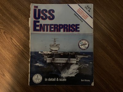
Detail and Scale Volume 39 The USS Enterprise Worlds First Nuclear Powered Aircraft Carrier CVAN-65 to CVN-65 by Bert Kinzy. I literally wore this book out with the binding finally failing. I had to save it by scanning each page and creating a PDF file. If you are building the 1981 to 1986 Enterprise this is a great book to have. It can be useful to my era also.

Reference (2).JPG

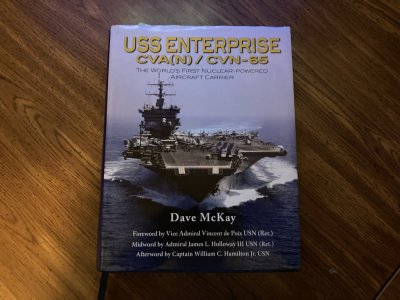
USS Enterprise CVA(N)-65/CVN-65 The World’s First Nuclear Powered Aircraft Carrier by Dave McKay This book has a detailed history going through each deployment and each yard period. It goes into specifics of equipment installations. It is a comprehensive history of the ship. But not a great source of photos.

Reference (1).JPG

I also got the following PDF/ e-Books

A Glenn Hoover Model Build Instruction Series; Detailed instructions on how to build kit 78007 CVN-65 USS Enterprise model 1/350 scale from Tamiya. The instructions also include the Eduard PE sets 53223, 53224, 53227, 53236, and 53237 for CVN-65 USS Enterprise. His books go step by step integrating the kit and Eduard instructions for you. He also includes constructing the hanger deck.

Model Builder International February 2015 Special Edition This is a special edition of the magazine focusing on Lou Carabott’s build of Tamiya’s 1:350 scale U.S.S. Enterprise CVN65. Lots of pictures including in process build photos.

Warship Profile 14 USS Enterprise CVAN-65 by Commander W. H. Cracknell U.S.N. a pictorial history up to 1969. This book does not have a great deal of information or great photos.

This is a Kindle book:

USS Enterprise (CVN-65) by Mark Evans, An engrossing day to day history of operations but not a great photographic source. I am currently reading the book and am up to events of 1968.

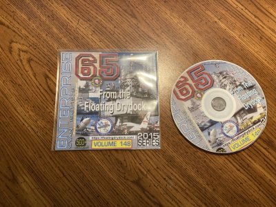
From Floating Drydock I also got a photodisk which has an abundance of photos that you won’t find elsewhere. https://floatingdrydock.com/index.htm .

IMG_0095.JPG

I used these websites:

https://www.navysite.de/cvn/cvn65.html great source the cruisebooks (yearbook) for each deployment and a large photo archive

https://www.navsource.org/archives/02/65.htm an online photo index

https://www.seaforces.org/usnships/cvn/CVN-65-USS-Enterprise.htm more online photos

https://www.imagicdigital.com/enterprise/index.html a virtual tour of the ship.

https://hyperscale.com/2019/galleries/enterprise350jg_1.htm a nicely done model by Jorge Evandro

http://www.modelwarships.com/reviews/ships/cv/cvn-65/350/cvn65.html Detailed description of his build by Kelly Quirk

https://hyperscale.com/2008/features/ussenterpriselc_1.htm Lou Carabott’s model less detail than the magazine article above

https://shipsofscale.com/sosforums/threads/tamiya-cvn65-enterprise-1-350.3143/ This is Norgales build from the SOS forum another good one.

https://www.carrierbuilders.net/gallery/20051020_CVN-65/20051020_CVN-65.htm Robert McGhee’s build. I especially enjoyed the tips section at the end.

http://www.gonavy.jp/CVW-NKf.html A history of CVW-14. You can use the links to check out other CAG histories

https://seaforces.org/usnair/VRC/Fleet-Logistics-Support-Squadron-50.htm Nice photos another source you can use for other units and ships

https://www.seaforces.org/usnair/VQ/Fleet-Air-Reconnaissance-Squadron-1.htm VQ-1 Photos

There are many more but these were my primaries

I also found sites for each type of aircraft and their respective squadrons just by using a search engine.

If you want to use 3-D printed parts for your model check out 3-D Wild, https://3d-wild.com/ and Model Monkey https://www.model-monkey.com/ Some of the items they have are pretty expensive. But the detail is incredible based on the photos. Black Cat Models has a lot of WW-II parts but many are still correct or can be adapted. I got a lot of my 3-D parts from Shapeways but the site went down in 2024. It is still there but I don’t think they work as a conduit to various designers like they used to. One of my favorite suppliers was Baconfist Models https://www.facebook.com/baconfist77/ he is still on Facebook. He is dedicated to providing parts for USN ships.

Extra (6).JPG
Items from shapeways and L'Arsenal


In part 3 I will begin construction.
 
Part 3
I decided to start by seeing if I could make the motorization system work. I know it isn’t a toy but from the earliest models that I made as a kid I have been fascinated by “working” features. I remember fondly, the great Monogram, Revell and Lindberg kits with opening canopies, removable hatches, folding wings, retractable landing gear and movable control surfaces. One of the last models I was working on before I went into the Navy was the Lindberg Blue Devil Fletcher Class Destroyer. You could build it with moving gun mounts, RADAR and props. So I just wanted to see if I could do something like that with the motor here.

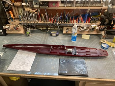
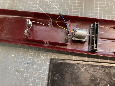
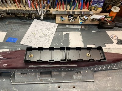
The Kit has an electric motor, battery box hardware, metal shafts and a one to four transmission. This is pretty ingenious as it turns the port and starboard shafts in opposite directions realistically. I wasn’t impressed with the rudimentary fast slow switch though. The switch fell apart after moving it from fast to slow just a few times. (It turns out that this part was broken in my kit. I discovered this when Modelar sent me his parts as you will read later). I certainly wasn’t going to stick the switch up through the slot in the flight deck anyway so I didn’t bother to repair it. My original goal was to connect the motor with the same power supply as the lights but to test the system I used the battery box molded in the lower hull which will accept 4 “D” Cell batteries to power the motor. I assembled the kit parts installing the motor, transmission and wiring. 4 Batteries is just way too many. The motor screams at warp 10 in fast and not much slower in slow position.

Motor Test (1).JPG

This is how Mini Hobby would have you connect everything up. The 4 "D" cell batteries would fit just ahead of the motor. Note the four large pins at the stern these are the rudder locaters.

Motor Test (2).JPG

The fast slow switch is at the top connected by the white, yellow and blue wires. Note the plastic tubing connectors on each shaft.

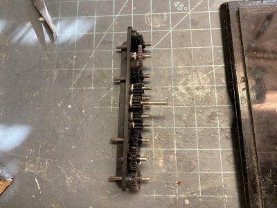
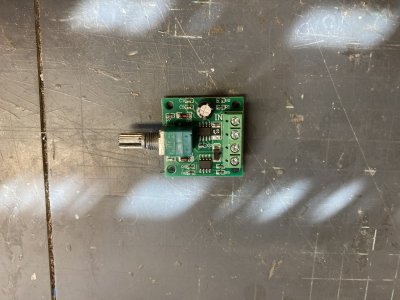
I tried just using just one battery and that reduced the power to a more reasonable amount so only about 1.5 volts are necessary. It is still a bit too fast but I found a fan control module on Amazon that was a good candidate for a speed control. One battery won’t power the motor through the fan control unit though. The 12 volt power supply for the LED lights does allow me to adjust the revolutions but it won’t go slow enough to look real. With 2 D cell batteries in series I get the right amount of current and voltage through the fan control unit to power the motor at a slow enough speed. That will be my final configuration, a separate battery box for the motor and the power supply for the lights. Unfortunately my transmission locked up repeatedly during the inadvertent high speed battery test. I traced this to the sloppy amount of play on each gear shaft. I corrected the play issue by making shims to restrict the amount each gear could move forward and aft in the transmission box.

Motor Re-work (4).JPG

The gears in the transmission can move forward and aft in the battery box. The middle gears all have one shim on each shaft. Eventually I will use two shims on all the larger gears one on each side. The grey gear at the bottom is my problem small gear. There is another grey gear at the top but it is the same size as the black gears. The gears are all coated with silicone grease.

Motor Re-work (6).JPG

The fan control module.

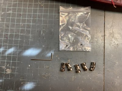
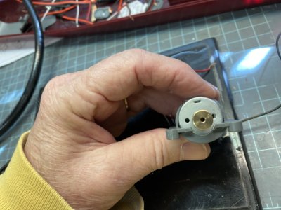
The system provided uses soft clear tubing to couple shafts together. These will eventually wear down and slip on the shafts or break if there is a bend at the joint. Once the model is assembled I won’t be able to make repairs. Radio control models use small metal couplers and universal joints to do this job so I purchased some. I got several of each type for less than $10.00 on Amazon. Originally I was going to use a straight coupler to connect the motor and transmission but I discovered that there was a difference in height between the motor output and the transmission input shafts. With a straight coupler it caused the transmission to bind. To correct this I made shims to raise the transmission which I glued to the lower hull. There is still some difference but not enough to effect coupling them together with a universal joint. I did have to shorten the motor shaft and press the transmission input shaft more aft to allow the universal to fit. I also had to modify the motor base. To couple the transmission to the propeller shafts required modifying the base of the transmission on the output side to allow universals to be installed.

Motor Re-work (3).JPG

Originally I thought to use a straight coupler to replace the tubing but ended up using 5 of the universal joints below.

Motor Re-work (7).JPG

Motor Re-work (2).JPG

The modification to the motor base plate.

Motor Re-work (11).JPG

I had to cut away sections of the transmission base to allow the universal joints to be connected.

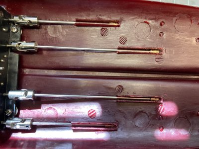
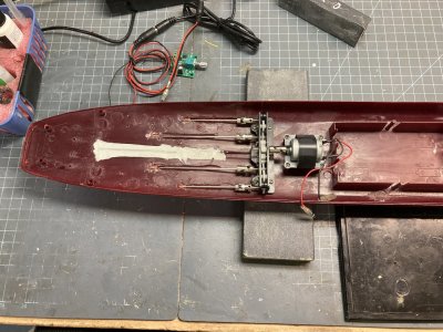
The hull and bearing hangers were supposed to be designed to be used with the metal prop shafts. The holes exiting the hull and through the bearings are too large and this allows the metal shafts to flop around unrealistically. Oddly the metal shafts don’t fit the props unless they are drilled out. Using 2 mm ID brass tubing I made “bearings” which could be inserted at each point and glued in place. The supplied metal shafts are 2mm. Since the bearing hangers needed to be in place to get the correct angle for the shaft through the hull I used Blue Tack to hold them in position so I could glue the through hull bearings. The hull bearings fit fine but there is a trough for each shaft that I had to enlarge to keep the shafts from dragging. This smooths out the shaft play.

Motor Re-work (18).JPG

Here you can see the amount of play around the bearing and shaft.

A second transmission problem surfaced, the number 2 shaft turned intermittently. The gear for this shaft is smaller than the other output gears! I played around moving that gear to other locations but it just moved the problem. The gear is not only smaller in diameter but the teeth appear stripped. This could have happened during the lock ups I experienced testing with the 4 “D” cells but the size issue came in the kit. The gear is a different color than all the others but one. I plugged the holes for that shaft and re-drilled the transmission in a slightly higher location ensuring the gears all meshed. This allows all four shafts to turn. I tried to find some way to contact Mini Hobby to see if I could get a replacement transmission but there is nothing in the instruction manual and for once the internet didn’t yield up a factory website. I did find an RC conversion kit by Tamiya for their Enterprise on e-bay for $99.00 plus shipping. That wasn’t going to fix my problem though. They don’t use a transmission but have 4 motors ganged in a row one for each shaft.

I got ahold of my friend Modelar and asked if he still had the transmission from his build. I offered to buy it but he is a generous man and just sent it to me. I had gotten mine to run as smoothly as it ever will but the unit from Modelar works so much better than the one I started out with. I can easily turn it by hand even with all the shafts connected. All his gears are the same material and color. I had to make the same mods to his transmission so I could use the couplers and prevent gear play with shims. I found two additional errors with my kit. One is problematic and the other an issue with a poorly written instruction manual.

Motor Final Test (2).JPG

This is Modelar's transmission. You can't imagine the difference in the two units.

The problematic:
The outboard shafts are shorter than the inboard. The outboard shafts have two bearings supporting them while the inboard shafts at .5 inch longer only have one. This looked wrong so I went to my reference photos and sure enough there should also be a second bearing on the inboard shafts also. The kit simply does not provide them and there are none in the Tamiya kit either so we know where the inaccuracy came from! To correct this oversight you will have to fabricate a pair of these.

FB_IMG_1680403432093.jpg

This is a photo of Enterprise in Drydock. The second set of bearings are clear on the near inboard shaft. This is one of the few photos showing the forward set of rudders. Notice the keel shape at the end.

The instruction issue:
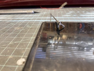
I noticed that the forward set of rudders have no locating holes. The Tamiya kit has you drill the holes for these from the inside. It is in their instructions in step 12. Mini Hobby forgot that little bit of information but the locators inside the hull are there. (Turns out it was a good idea to obtain that set of Tamiya instructions) The locating holes for all four rudders on the Mini Hobby kit are tubes which pass through the aft upper hull part to aid in locating the bottom and top correctly. I can’t tell if the Tamiya kit has long tubes from the instruction drawings.

The prop shafts in the Tamiya kit are different. Theirs are all plastic shafts that have the fairings attached which are then glued into recesses in the hull. The Mini Hobby kit has the fairings molded onto the hull. The shafts are straight metal rods. This was probably a good decision on their part since there seem to be plenty of fit issues in their molds. There are no plastic parts for the shafts. All of the bearings and their struts have a nasty step along the seam line. Be prepared for some major sanding on very delicate parts. I managed to break some struts off while sanding. I believed it was because I was too ham fisted. After sanding the seam lines on the struts I became concerned that they had become too flimsy to hold up under operation. I found a photoetch fret in my spare parts bin that was the right width. I cut sections of the fret to stiffen the struts. The metal reinforcements are all glued to the inside faces of the struts.

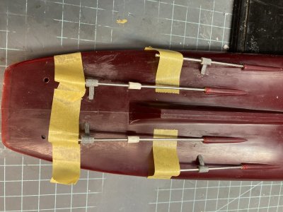
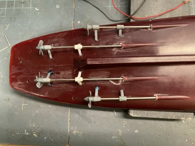
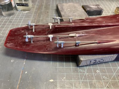
I drilled out the holes for the rudders. These provide landmarks to place the second bearings on the inboard shafts. Using pieces of Evergreen tubing cut to the same length as the kit supplied bearings I made two new ones. I cut off lengths of brass tube to fit and drilled out the tubing and glued the brass in place. I slid these on the prop shafts and used bits of Blue Tack to hold them in the correct positions. Now the model could be used as a jig to fabricate the struts. I cut sections of Evergreen strip for struts and glued them to the bearings. Once they had dried I sanded them to match the kit parts. I drilled locating holes in the hull and then put the locating pins on each strut to keep everything lined up. (One of these new bearings fell onto the garage floor and disappeared. The garage floor is similar to the carpet monster. I had to make another and I still haven’t found the missing one).

Motor Re-work (24).JPG

This is an in process photo while I make the new bearings.

Motor Final Test (4).JPG

The new bearings in white.

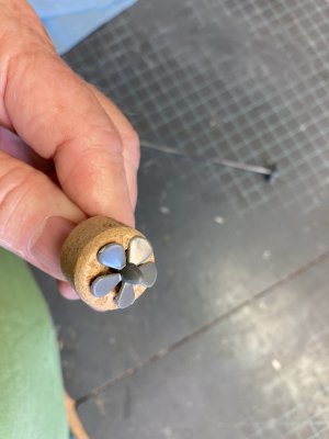
I attached each bearing to the hull with Micro Mask solution which provides a good temporary bond. These were then reinforced with masking tape and allowed to dry. I glued each pair of props to the shafts. The props are molded differently for the port and starboard to represent the different rotations for each side so don’t mix them up. That is pretty nice attention to detail. As I cleaned up the parts I found it very easy to damage the blades. They are also fragile like the bearing struts. One blade was almost ready to break just from cutting from the sprue. I was using an almost new pair of Tamiya nippers. I fixed the props to the shafts with superglue after repairing about 3 blades. Now I could slip each shaft into place and attach it to the universal joints. When the input shaft is turned by hand everything rolls over nice and smooth.

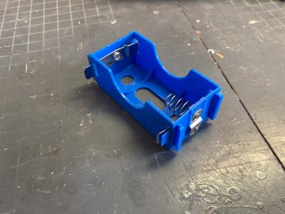
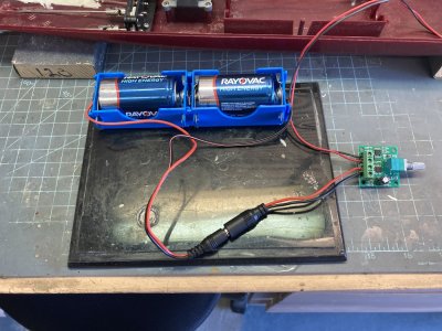
I haven’t thought out how the ship will be mounted to its display base yet although I have a nice piece of clear pine for it. So at this point I am not ready to drill any holes in the bottom. I didn’t want a long wire to get in the way while I’m building so I removed the wiring from the motor and attached two short leads one red and one black maintaining the polarity from the kit wiring. To make connections easier I used motorcycle wiring connectors which I installed myself. I have the tools and connectors from the time I worked as a motorcycle mechanic. I attached leads for the fan control module and put the correct connectors on each of them. Since I had determined that I needed a separate power source using two “D” cell batteries I looked for a battery box. I found a set of 4 single boxes on Amazon which can be ganged in series or parallel. Using 2 in series I was able to make up a permanent battery pack.

Motor Re-work (30).JPG.JPG

Modular battery boxes.

Motor Re-work (26).JPG.JPG

The battery boxes ganged in series with the speed control connected

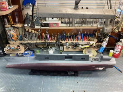
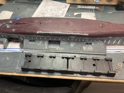
With everything hooked up I can adjust the motor speed to a reasonable level. I’ll have the power supply, battery box and other components under the display base. With my test complete I will remove all the motor components and bag them into labeled zip bags for port and starboard shafts. They will be installed permanently later after the major hull work is done and I can rig a temporary base. My next chapter will be dealing with the huge sprue attachment on the bottom center of the hull, the keel modification I want to make and fitting the upper and lower hull together.

Motor Re-work (19).JPG

The giant sprue connection

Motor Final Test (3).JPG

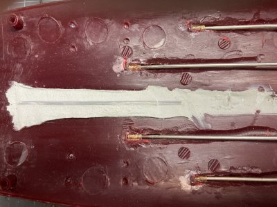
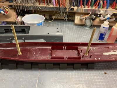
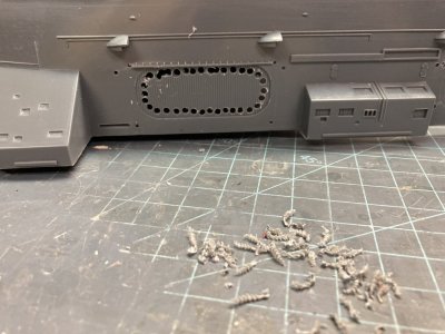
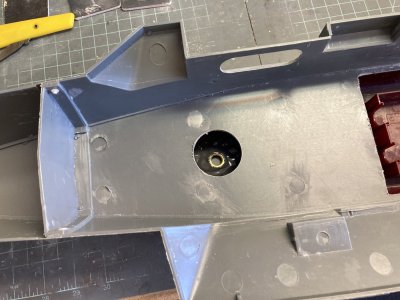
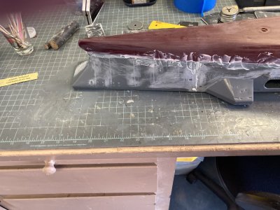
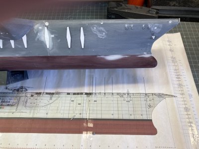
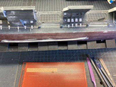
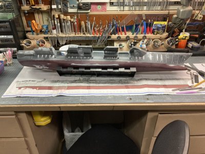
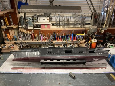
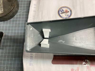
I removed the fences around the prop shafts and ground them out to stop the shafts from dragging. I placed a .060 plastic keel in the centerline of the cavity and filled it with Bondo auto body filler in preparation for keel modification.

Motor Final Test (1).JPG

Final installation

Below is a short video of the system working and I apologize in advance for the quality and audio I am not a videographer.

 
Last edited:
Back
Top