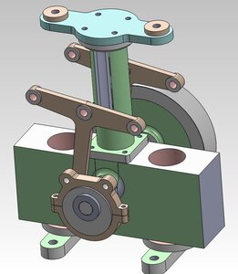
My non-boat Hobby

I currently use Solidworks to make 3D models, and I 3D print the patterns.
Very cool Pat. In addition to fabrication and model building, I have been a motorcycle mechanic most of my life. I still have 4 dirt bikes and 2 quads. I am planning to do a frame up restoration on one of my quads. It is a 1985 Yamaha 350 Banshee... a very classic ATV because it uses a 350cc 2 cylinder 2-stroke engine from a streetbike. That will be my project for next spring.

I have 2 commercial lasers and a CNC machine. We are planning to get a 3D printer next year. My wife and I own a small business etching custom cutting board gifts and glass barware... she runs the business and I run the shop!!

I use Corel Draw for 2D drawing and Vectric Aspire for 3D modeling and CNC toolpathing.

It looks like we have slightly different but oddly similar interests !!!!
 
Last edited:
I did 2D cad work (autocad) for many years, but I found the transition to 3D modeling to be very confusing.
I think it took me a full year to understand how to correctly approach 3D modeling.

Determining a good initial approach is critical when modeling a complex part.

That 2 cylinder 2-stroke sounds like a beast.

My beloved XR200 is missing at higher rpms. I guess I need to change the plug first, but after that, would you look at ignition coil or carb?

.
 
XR200 is missing at higher rpms. I guess I need to change the plug first, but after that, would you look at ignition coil or carb
The XR200 is very famous and reliable. Change the plug, clean the carb.. If it still misses, check that the timing plate has not moved. It is rare that the coil will go bad but sometimes they do.

That 2 cylinder 2-stroke sounds like a beast.
Yes indeed it is!!! The motor itself traces its heritage back to GP racing. Very easy to tune for a large power increase.

I found the transition to 3D modeling to be very confusing.
I completely agree with you on that!!! I am fortunate to have a background in Information Technology so I tend to pick up software pretty quickly.

Let's stay in touch... I love all things with parts that assemble.... mechanical, models, motors, wood, plastic, it doesn't matter!!!
 
My internet is down.
When it comes back up, I will elaborate a bit more about 3D modeling.
 
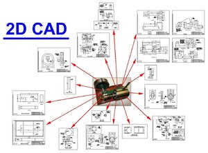
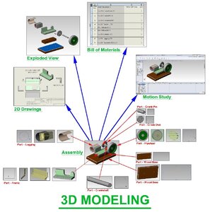
Here are a couple of charts I created to help me clarify in my head what I was doing with 2D CAD, and how that differed from what I was trying to do with 3D modeling.

For 3D modeling, it basically requires being able to visualize how to take a complex object and slice it so that it can be broken down into its basic components.
You have to find a good place to make a section for each piece of the overall part.
Where you begin to slice makes a big difference in how easy it will be to make the initial 3D model, and how easy it will be to modify it once it has been created.

The first few 3D models I created were "Frankenmodels", and when I would try to modify them, they would basically self destruct.


2D-CAD-01.jpg

3D-Modeling-01.jpg
 
Here are a couple of charts I created to help me clarify in my head what I was doing with 2D CAD, and how that differed from what I was trying to do with 3D modeling.
Hi Pat. Yup, it looks like you have the basic concept correct in your head. It is indeed difficult to transition from 2D to 3D, especially for complex machines like you are drawing. All of my drawings have been for wooden model ships which have no moving parts and require less precision.

Here are my steps:

1. Draw 2D elevations for each individual part separately. This will provide exact measurements and scaling.
2. Render each 2D part in 3D. This is difficult depending on software and requires closed vectors. I use Vectric Aspire and am not familiar with Solidworks.
3. Run 3D rendering simulations on each 3D part over an over until the part is perfect. Also software dependent and time consuming.
4. Put each 3D part together in the simulation by grouping to see how they fit. I call this 3D assembly. Software dependent.
5. Repeat steps 1 - 4 until all parts have been created, rendered in 3D and fit together properly.
6. Create a Bill of Materials for each 3D part (I see you do that already... good).
7. Take each individual 3D part and render it for fabrication. Software dependent and fabrication dependent (toolpathing for CNC, STL file for 3D printing).
8. Fabricate prototypes out of cheap material for each part.
9. Assemble prototypes into final prototype model and inspect for fit, precision, and workmanship.
10. Repeat steps 1 - 9 until prototype model is satisfactory.
11. Fabricate production parts from production materials (may also require mould creation if casting from 3D prints)
12. Assemble production model.

Once the design for fabrication is perfected, the parts can be reproduced as many times as needed (manufacturing).

In general, the better the software (i.e. more expensive) the easier this process is. Being able to run simulations inside the computer is key.

Does that match how you think about it???
 
Does that match how you think about it?
I found an online boat design program, but my knowledge of boat building and 3D modeling at the time were somewhat limited.
My boat building knowledge is still somewhat limited, but much better than it use to be.

My basic understanding of boat building is "nothing is straight", and that is a bit of a problem.
I discussed planking a boat with the boat building guy at an adjacent table at NAMES in 2019, and I wish I had been able to discuss more with him.
He had some serious boat models, and told me some good do's and dont's, which unfortunately I have forgotten now (should have written it down).
Seems like he said don't make the planking super thin at the ends, but stop it short, and squared off, or vice versa.
Perhaps I will seen him again if they ever have another NAMES.

So it would seem that 3D software and CNC would be the perfect mix for boat building, assuming you knew how to do both.
I don't do CNC, and have resisted doing things by CNC, just because I am into to many things already.

3D printing simplifies pattern making a lot, but again that assumes that you know how to do 3D modeling and how to modify a 3D model to make a pattern (two different things).

Compound curves can challenge 3D programs.
I use Solidworks, and sometimes it works, and sometimes the shape is too complex.

I have used lofted elipses for spoke sections, and loft the spoke along a non-linear path.
That gives a good approximation of how many of the old flywheel spokes were made.

For an engine that I only have a photo of, I lay a grid over the photo, and then model one part at a time, using the grid to maintain the correct proportion between parts and pieces.
Sometimes I don't know the size of the engine, but as long as the proportions are accurate, you can build a scale model; you just don't know the exact scale.
You can make an engine any size, even if you don't know the scale.

I look at one part at a time, such as the cylinder, and then have to figure out which plane to begin on, how to work out from that plane, and then where to put secondary planes, so that things like cylinder flanges will remain the same size if the cylinder size is lengthened.

Basically I find the fundamental shape of a part, cut a virtual section in the appropriate plane, and then draw that section in AutoCad.
I import the section into Solidworks, and then use that to begin the model.
It is much faster for me to do 2D work in AutoCad than in the 2D part of Solidworks.

When I began 3D work, I generally made sections that were too complex, and thus had trouble modifying them later.
Now I keep my sections as simple as possible, and use more sections that are simple.
If I have a problem with one section, and that section is simple, then there is little chance of the other parts of the model not working correctly.

I don't really do rendering, and I guess because I did not buy the render package with Solidworks.
I have done some rendering in Alibre.
Generally I don't need renderings, since I build the engine and can look directly at that.
Renderings do look nice if done correctly, and they look a lot better than just the plain 3D model.
Sometimes people go overboard with rendering, and it looks too shiny and unrealistic (almost plastic-like).

Once each part is complete, I start an assembly, and test the motion of each part as I add them.
If you wait and assemble all the parts at the end, then you may discover multiple problems that can be very difficult to troubleshoot.
I run an engine in simulation to make sure there are not conflicts.
Solidworks is extremely picky about assemblies that have motion in simulation, and that is a good thing I guess, because it you can get it to run in simulation, then it will definitely run in the real world.

Then I create 2D drawings in Solidworks, derived from the 3D models, and import that back into AutoCad.
Again, I can control 2D far better in AutoCad.

From an assembly I can create an exploded view.
I really don't use Bill of Materials, but instead generate that manually, but it is a powerful feature if you take the time to set it up correctly.

3D modeling is nice because I can generate the model for one engine, and then 3D print that engine at multiple scale factors.
Some folks like larger engine sizes, and some prefer smaller engines due to the limitations of their lathe and mill.

I suppose you could 3D print all the parts for a boat, but they would be in plastic, not wood.
So I see the need for CNC in order to make a wood boat (many/most boat models seem to be made with wood).

So its as simple as that.

I told a buddy of mine "it would be easy to cast that engine yourself; all you need to do is build a foundry".
His reply was "yes, and I could easily teach a snake to tap dance, after I got the shoes on".

.
 
Last edited:
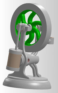
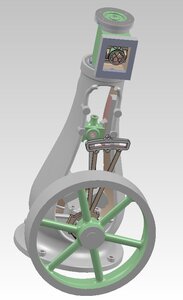
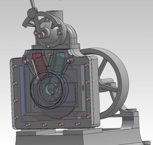
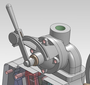
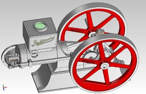
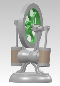
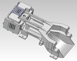
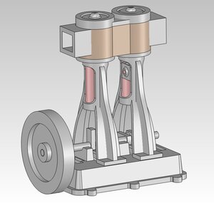
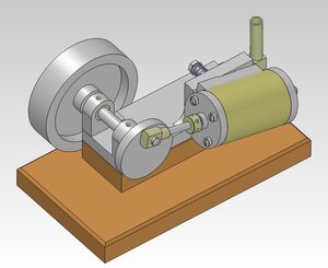
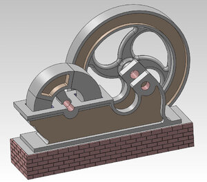
Here are some 3D models I am working on, in various stages of completion.
The frame for the Cretors No.06 (first photo) was rather tricky, as was the bottle engine frame.

The Soule Speedy Twin has been a nightmare to model, but I am getting there.
Luckily I have a real engine I can measure, else I would not be able to model that engine accurately.


Assembly-01.jpg

Bottle-Assembly-07-10-13.jpg

Dake-Assembly-11.jpg

Dake-Valve-04.jpgGalloway-Overall.jpg

Image4.jpg


Image12.jpgMarine-Compound-TALL-05.jpg

N0-21-Assembly-06.jpg

NO-04-Robertson-Assembly-06.jpg

Strap-Top-08.jpg
 
Back
Top