





Welcome to my first build log of the Navio Rayo Puesto de Combate kit, or in English, literally word for word, Ship of the Line Lightning Position of Combat , or as I call it, using the Spanish name of the ship, Ship of the Line Rayo Combat Station kit made by Disarmodel. The kit shows a portion of its two gun decks plus the spar deck. There is a total of 5 cannons in the kit. The scaling of the kit is 1:32.
The Spanish Navy ship Rayo was initially an 80-gun ship of the line. Construction on her began in Havana, Cuba in 1747. She was commissioned in January 1751 and sailed to Cadiz, Spain. Between 1803 and 1805 she was rebuilt in Cartagena, Spain, adding a third gun deck, now having a total of 100 guns on the ship.
Rayo was dismasted in the Battle of Trafalgar on October 21, 1805. It was during that battle that Lord Admiral Horatio Nelson was mortally wounded. Two days later she was captured by the 74-gun Ship of the Line HMS Donegal and a British prize crew was placed on board. Unfortunately, she ran aground during a storm on October 26, 1805 and was burnt by the prize crew 5 days later, as they could not make the Rayo seaworthy.
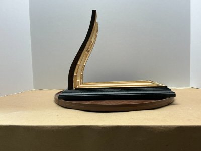
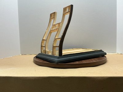
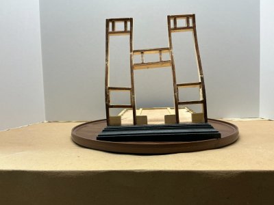
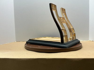
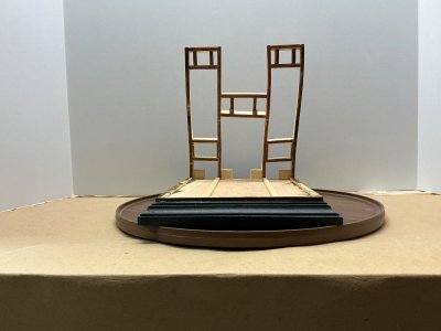
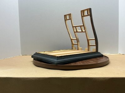
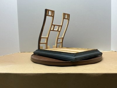
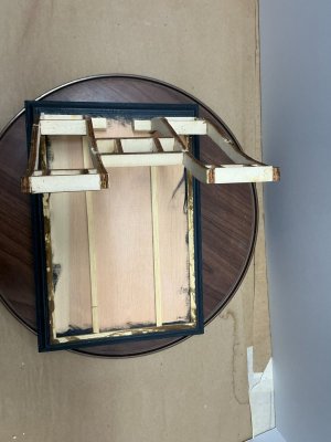
As you can see from the attached photos, I have attached the ribs (Part 2) and the frames for the five gunports to the display stand (Part 1). I have also glued the support beams (Part 8) of the lowest gun deck to the stand.
When I initially glued the ribs to the display stand, it turned out the ribs were not aligned properly with each other. Luckily, the glue had not yet hardened, so I was able to remove the ribs. I then built the left two ribs together on a flat surface, using the spacers (Part 4) between the two ribs, to ensure the ribs aligned properly. I repeated this for the right two ribs and their spacers. Next, I glued the spacers (Part 5) between my two assembles, so that all four ribs were now aligned correctly. I then glued the additional spacers (Parts 6 and 7) in place. Finally, I glued the ribs to the base.
A word of warning to someone who builds this kit in the future. It turns out the spacing that Disarmodel specifies for the distance between the two Part 7 spacers is about 4 mm less than the width of the laser-cut plywood upper deck gunport door (Part 85). If I knew this prior to gluing the spacers in place, I would have repositioned the Part 7 spacers prior to such gluing to make the space slightly larger than the width of Part 85. The solution was simple as I just sanded down those spacers so that Part 85 just fit between them. I discovered this as the gunport openings for the lower deck gunports seemed to me to be much wider than their gunport doors (Part 84), so I tested both Parts 84 and 85. It turns out the lower gunport openings are 8 mm wider than Part 84 is wide. To fix this, I used the scrap laser-cut board wood from which Parts 4 through 7 were on, to cut out spacers like Parts 6 and 7. I glued them up against the hull ribs (Part 4), which since the laser-cut board was 6 mm thick, meant I had to remove about 2 mm of each of my homemade spacers for the lower gun deck gunport openings, so that Part 84 would just fit in the gunport opening. Since these were plywood, I was able to use my Xacto chisel blade to remove a couple of the individual woods that made the plywood, prior to gluing them to the ribs and then only perform a little sanding to get the size I needed.
As you can see from the attached photos there were five support beams (Part 8) for the lowest gun deck, four long ones (215 mm) and one shorter one (170 mm). However, the kit came with only three plywood strips (per the parts list) to make the beams. Each of the supplied plywood strips was 6 mm x 3 mm x 400 mm, which was longer than the long support beam (215 mm) but shorter than twice the length of that beam (430 mm). If the three plywood strips had been at least 430 mm, then each of the five support beams would have been made from a single piece of plywood, per the picture in the instruction manual. Since that was not the case, I made one of the 215 mm beams and the 170 mm beam from one 400 mm plywood strip. I then made two of the three remaining 215 mm beams from each of the remaining 400 mm strips. I glued the 170 mm beam across the back of the stand with two of the 215 ones on the outer side edges of the stand. The remaining single-piece 215 beam was one of the two inner beams. The remaining inner beam was made from one of the left over 185 mm pieces and 30 mm of the other remaining 185 mm piece. I wanted the visible beams (the outer two 215 ones and the back 170 mm one) to each be made from a single piece of plywood. Since the inner beams will be covered by the decking, you will never know that one of them was made up of two pieces of plywood and not a single strip. Disarmodel should have made two of the plywood strips at least 430 mm in length or have supplied five wood strips, each at least 215 mm in length.
Another note about the lower deck support beams is that the instruction manual shows them as all being from a single strip of walnut wood and not the provided plywood strips. Also, the three videos I saw online of others having built this model (circa 2019), show a single strip of walnut for each beam. I am guessing that Disarmodel switched from walnut to plywood, but did not make them long enough (400 mm versus 430 mm) nor changed the photo in the instruction manual to show the use of plywood versus walnut.
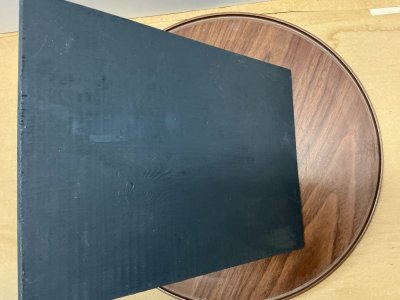
I painted the visible part of the display stand with one coat of Vallejo Black Primer and then two coats of Model Expo Icon/Cannon Black paint.
I treated the outer edges of the two most outer ribs and the edge of the outer deck support beams with one coat of Model Expo Pre-Stain Wood Conditioner, three coats of OcCre Walnut Dye with lightly sanding the stained area with 320-grit sandpaper after each coat dried and then two coats of OcCre Satin Varnish, again using the same sandpaper after the first coat dried, but using a green kitchen scouring pad instead of the sandpaper after the final coat dried. I have used this treatment and methodology since 2022 which is when I built OcCre’s RMS Titanic kit. This methodology is what OcCre suggested making the Titanic’s decks. I really liked the way those decks came out, and so, I have repeated that treatment and process for all my unpainted wood in my builds.
Please enjoy the attached photos.
All comments or questions appreciated.
The Spanish Navy ship Rayo was initially an 80-gun ship of the line. Construction on her began in Havana, Cuba in 1747. She was commissioned in January 1751 and sailed to Cadiz, Spain. Between 1803 and 1805 she was rebuilt in Cartagena, Spain, adding a third gun deck, now having a total of 100 guns on the ship.
Rayo was dismasted in the Battle of Trafalgar on October 21, 1805. It was during that battle that Lord Admiral Horatio Nelson was mortally wounded. Two days later she was captured by the 74-gun Ship of the Line HMS Donegal and a British prize crew was placed on board. Unfortunately, she ran aground during a storm on October 26, 1805 and was burnt by the prize crew 5 days later, as they could not make the Rayo seaworthy.
As you can see from the attached photos, I have attached the ribs (Part 2) and the frames for the five gunports to the display stand (Part 1). I have also glued the support beams (Part 8) of the lowest gun deck to the stand.
When I initially glued the ribs to the display stand, it turned out the ribs were not aligned properly with each other. Luckily, the glue had not yet hardened, so I was able to remove the ribs. I then built the left two ribs together on a flat surface, using the spacers (Part 4) between the two ribs, to ensure the ribs aligned properly. I repeated this for the right two ribs and their spacers. Next, I glued the spacers (Part 5) between my two assembles, so that all four ribs were now aligned correctly. I then glued the additional spacers (Parts 6 and 7) in place. Finally, I glued the ribs to the base.
A word of warning to someone who builds this kit in the future. It turns out the spacing that Disarmodel specifies for the distance between the two Part 7 spacers is about 4 mm less than the width of the laser-cut plywood upper deck gunport door (Part 85). If I knew this prior to gluing the spacers in place, I would have repositioned the Part 7 spacers prior to such gluing to make the space slightly larger than the width of Part 85. The solution was simple as I just sanded down those spacers so that Part 85 just fit between them. I discovered this as the gunport openings for the lower deck gunports seemed to me to be much wider than their gunport doors (Part 84), so I tested both Parts 84 and 85. It turns out the lower gunport openings are 8 mm wider than Part 84 is wide. To fix this, I used the scrap laser-cut board wood from which Parts 4 through 7 were on, to cut out spacers like Parts 6 and 7. I glued them up against the hull ribs (Part 4), which since the laser-cut board was 6 mm thick, meant I had to remove about 2 mm of each of my homemade spacers for the lower gun deck gunport openings, so that Part 84 would just fit in the gunport opening. Since these were plywood, I was able to use my Xacto chisel blade to remove a couple of the individual woods that made the plywood, prior to gluing them to the ribs and then only perform a little sanding to get the size I needed.
As you can see from the attached photos there were five support beams (Part 8) for the lowest gun deck, four long ones (215 mm) and one shorter one (170 mm). However, the kit came with only three plywood strips (per the parts list) to make the beams. Each of the supplied plywood strips was 6 mm x 3 mm x 400 mm, which was longer than the long support beam (215 mm) but shorter than twice the length of that beam (430 mm). If the three plywood strips had been at least 430 mm, then each of the five support beams would have been made from a single piece of plywood, per the picture in the instruction manual. Since that was not the case, I made one of the 215 mm beams and the 170 mm beam from one 400 mm plywood strip. I then made two of the three remaining 215 mm beams from each of the remaining 400 mm strips. I glued the 170 mm beam across the back of the stand with two of the 215 ones on the outer side edges of the stand. The remaining single-piece 215 beam was one of the two inner beams. The remaining inner beam was made from one of the left over 185 mm pieces and 30 mm of the other remaining 185 mm piece. I wanted the visible beams (the outer two 215 ones and the back 170 mm one) to each be made from a single piece of plywood. Since the inner beams will be covered by the decking, you will never know that one of them was made up of two pieces of plywood and not a single strip. Disarmodel should have made two of the plywood strips at least 430 mm in length or have supplied five wood strips, each at least 215 mm in length.
Another note about the lower deck support beams is that the instruction manual shows them as all being from a single strip of walnut wood and not the provided plywood strips. Also, the three videos I saw online of others having built this model (circa 2019), show a single strip of walnut for each beam. I am guessing that Disarmodel switched from walnut to plywood, but did not make them long enough (400 mm versus 430 mm) nor changed the photo in the instruction manual to show the use of plywood versus walnut.
I painted the visible part of the display stand with one coat of Vallejo Black Primer and then two coats of Model Expo Icon/Cannon Black paint.
I treated the outer edges of the two most outer ribs and the edge of the outer deck support beams with one coat of Model Expo Pre-Stain Wood Conditioner, three coats of OcCre Walnut Dye with lightly sanding the stained area with 320-grit sandpaper after each coat dried and then two coats of OcCre Satin Varnish, again using the same sandpaper after the first coat dried, but using a green kitchen scouring pad instead of the sandpaper after the final coat dried. I have used this treatment and methodology since 2022 which is when I built OcCre’s RMS Titanic kit. This methodology is what OcCre suggested making the Titanic’s decks. I really liked the way those decks came out, and so, I have repeated that treatment and process for all my unpainted wood in my builds.
Please enjoy the attached photos.
All comments or questions appreciated.