Hi All
This is a departure from my previous builds and a venture into model engineering. Some may say this is a leap into the extreme, akin to building a fully framed ship as your first model.
Yes, this is probably one of the most complex marine steam engine models available in castings.
I am not a complete rookie, I was trained in machining and bench fitting way back in college plus I have worked in engineering for the last 36 years.
On to the subject, I believe Bolton's design is based on an Australian Ferry engine. The engine incorporates an integral Condenser, an air pump and two water pumps.The three pumps are mechanically driven by the engine itself.
For those unfamiliar with steam engines, the triple expansion design reuses steam twice to maximise efficiency.Steam enters the small volume high pressure cylinder. The exhaust steam from this cylinder then passes to the Intermediate pressure cylinder. The exhaust steam from this cylinder then passes to the largest, Low pressure cylinder. The exhaust gasses from this last cylinder are "pulled" out by the vacuum created by the Air pump and into the condenser.The condenser has a water jacket to help cool the steam which is circulated by one of the water pumps.The second water pump is used to keep the Boiler replenished with water.
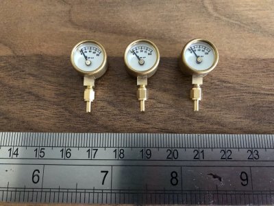
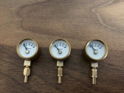
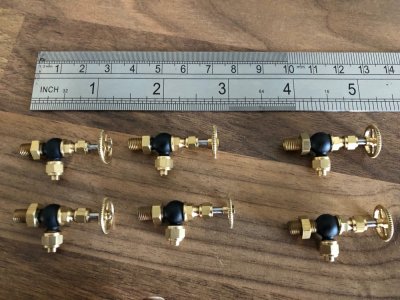
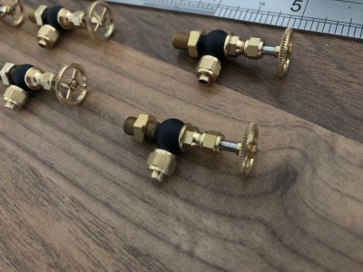
The model will work as the prototype on live steam. Along with the obvious machining of the engine itself, there is a plethora of valves plus a copper tube matrix to build inside the Condenser.
This project is one of three "Bucket list" projects that I would like to finish before my time is up. My Imara build with two Steam Engines is the first, this is the second. I have found a copy of a book covering the build of the third. Similar price second hand as one of Bordroit's Monographs but worth it given the detail of the model covered.
I have reached the end of what I can tolerate with my cheap 7 x 12 mini lathe. It simply cannot do what I am now asking of it. With that in mind, I have ordered a 10 inch swing 22 inch between centres medium size lathe with stand and digital readout, that is being delivered on Wednesday along with an engine crane on hire to lift and install the thing.
Enough waffle, time for some pictures
Some snaps from the drawings showing the general arrangement. The model will be 10 inches long when complete and weigh roughly 22lbs


Now the castings.These obviously all require extensive cleaning up and machining. Everything os cast in Gunmetal apart from the base, which is aluminium.
The two cylinder blocks, three valve chests and two valve chest covers. The block is split into two and will bolt together sandwiching the Intermediate pressure valve chest.

The aluminium baseplate which houses the main bearings and crankshaft. The six supporting columns, two of which include the condenser casing. The condenser end caps are also shown

The top and bottom cylinder covers and the two piece pistons. The round lugs are designed to be used for initial chuck holding in the lathe and are removed during the later machining stages. Time will tell how useful these are.

The straps for the eccentrics (used to control the valves), the big end bearings, valve blanks and buckles and finally gunmetal bar to make the main bearings.

Finally, the casings for air pump, water pumps, valve rod guides and steam Globe valve.
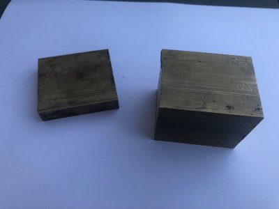
In addition, numerous sizes of steel bar stock, bronze bar stock plus @ 500 fixings will need to be purchased to build the model

This is a departure from my previous builds and a venture into model engineering. Some may say this is a leap into the extreme, akin to building a fully framed ship as your first model.
Yes, this is probably one of the most complex marine steam engine models available in castings.
I am not a complete rookie, I was trained in machining and bench fitting way back in college plus I have worked in engineering for the last 36 years.
On to the subject, I believe Bolton's design is based on an Australian Ferry engine. The engine incorporates an integral Condenser, an air pump and two water pumps.The three pumps are mechanically driven by the engine itself.
For those unfamiliar with steam engines, the triple expansion design reuses steam twice to maximise efficiency.Steam enters the small volume high pressure cylinder. The exhaust steam from this cylinder then passes to the Intermediate pressure cylinder. The exhaust steam from this cylinder then passes to the largest, Low pressure cylinder. The exhaust gasses from this last cylinder are "pulled" out by the vacuum created by the Air pump and into the condenser.The condenser has a water jacket to help cool the steam which is circulated by one of the water pumps.The second water pump is used to keep the Boiler replenished with water.
The model will work as the prototype on live steam. Along with the obvious machining of the engine itself, there is a plethora of valves plus a copper tube matrix to build inside the Condenser.
This project is one of three "Bucket list" projects that I would like to finish before my time is up. My Imara build with two Steam Engines is the first, this is the second. I have found a copy of a book covering the build of the third. Similar price second hand as one of Bordroit's Monographs but worth it given the detail of the model covered.
I have reached the end of what I can tolerate with my cheap 7 x 12 mini lathe. It simply cannot do what I am now asking of it. With that in mind, I have ordered a 10 inch swing 22 inch between centres medium size lathe with stand and digital readout, that is being delivered on Wednesday along with an engine crane on hire to lift and install the thing.
Enough waffle, time for some pictures

Some snaps from the drawings showing the general arrangement. The model will be 10 inches long when complete and weigh roughly 22lbs


Now the castings.These obviously all require extensive cleaning up and machining. Everything os cast in Gunmetal apart from the base, which is aluminium.
The two cylinder blocks, three valve chests and two valve chest covers. The block is split into two and will bolt together sandwiching the Intermediate pressure valve chest.

The aluminium baseplate which houses the main bearings and crankshaft. The six supporting columns, two of which include the condenser casing. The condenser end caps are also shown

The top and bottom cylinder covers and the two piece pistons. The round lugs are designed to be used for initial chuck holding in the lathe and are removed during the later machining stages. Time will tell how useful these are.

The straps for the eccentrics (used to control the valves), the big end bearings, valve blanks and buckles and finally gunmetal bar to make the main bearings.

Finally, the casings for air pump, water pumps, valve rod guides and steam Globe valve.
In addition, numerous sizes of steel bar stock, bronze bar stock plus @ 500 fixings will need to be purchased to build the model

Last edited: