Well done Nigel. Its a great project. 
-

Win a Free Custom Engraved Brass Coin!!!
As a way to introduce our brass coins to the community, we will raffle off a free coin during the month of August. Follow link ABOVE for instructions for entering.
You are using an out of date browser. It may not display this or other websites correctly.
You should upgrade or use an alternative browser.
You should upgrade or use an alternative browser.
O.B. Bolton Marine Triple Expansion Steam Engine using castings by AJ Reeves, drawings by John Bertinat
Well done Nigel. Its a great project.
Thankyou Bryan, it's good fun as I am well out of my comfort zone
Nigel, it's a real beauty and I'm learning a lot. Enjoy your new project! Magic Mike
Nigel, it's a real beauty and I'm learning a lot. Enjoy your new project! Magic Mike
Thanks Mike, I am trying to go into as much detail as possible without making the log 500 pages long
Bolton part six
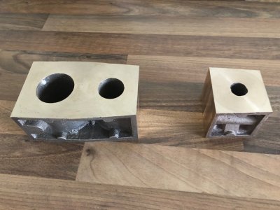
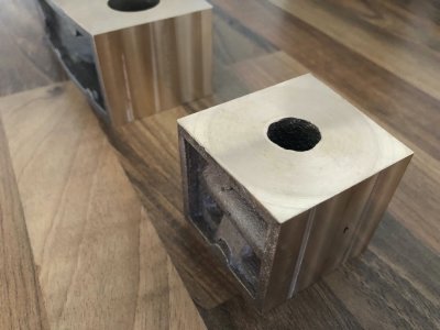
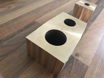
After facing the top and bottom of the cylinder blocks to give me the correct thickness of 2" I have turned my attention to bringing them to length. This was accomplished in the mill first with the castings clamped directly to the table (with parallels underneath to get a rough cut. Milling these vertically with a long 18mm cutter gave square ends in relation to the previously machined faces. The pieces were then placed in a machine vice so I could carry out final finishing cuts with the end of the milling cutter.
Both castings have been made shorter than the drawing to allow for 1/64" gaskets at each joint. It is my intention to carry out boring of the cylinders with the cylinders and middle valve chest bolted together and with gaskets installed. This will ensure the centres of the bored cylinders are correct when all is bolted together.
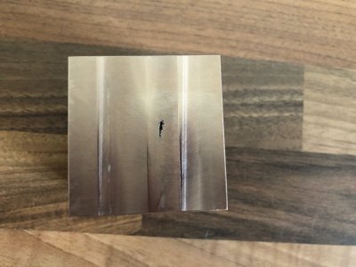
I am a little disappointed by the amount of blow holes/porosity in these castings. this is mainly on the thin webs of the large block but there id one big one right in the area of the high pressure cylinder exhaust passage. Most of this will be removed when machining the passage but I may have to do a local repair with silver solder. I dare say I could try Reeves for replacements but feel I may have the same issue with these. The other blow holes are less of a concern as they can be filled with JB weld prior to painting the blocks.


Last edited:
Hi ShotaDear Nigel
Its looks a unique project, I will keep following with great curiosity
There are quite a few examples of this engine in circulation. Unlike model boats, a few pop up in Model Engineering auctions and quality examples demand premium money
Bolton Part seven
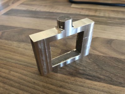
This is where I deviate from normal practice and go my own way using what I have learned from the day job.
The valve chests are traditionally machined on the lathe using an elaborate system of faceplate with angle block attached so the valve rod passages can be drilled through top and bottom faces insuring alignment.
Given there is not a blind hole on this engine at the top of each chest as in most Stuart Engines I plan to do most of the work on the mill and use datum faces. An edge finder and the DRO will be used to drill these important holes.
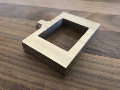
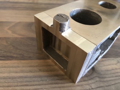
The first step is to take the valve chests to thickness and square top and bottom faces to the same height as the block. The boss for the Valve rod gland is left untouched for now. This will be turned in the lathe in the 4 Jaw chuck as the last operation with the hole used for reference to centre it.
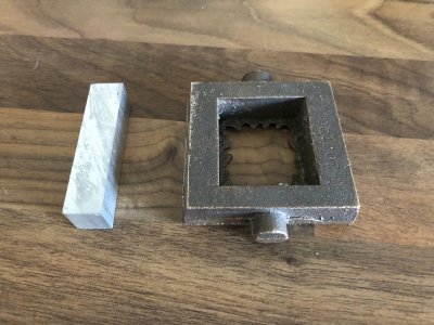
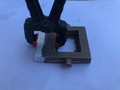
The intermediate Steam valve chest is tapered so this causes an issue as the is no accurate datum face. I have glued a piece of Aluminium to the side of this chest using JB weld. This chest will then be machined as the previous one but I will end up with a square face on the side to reference the edge finder. This aluminium piece will be machined off when the assembled block has it's taper machined.
As a side note, following John's advice, I have ordered a book on this build, some additional drawings along with Bolton's Original drawings for this engine from E and J Winter in NSW, OZ. Postage was quite reasonable and hopefully should land between 6 and 21 working days.


Last edited:
Hi Nigel. I want to wish you a Happy Birthday! Enjoy this day.
Regards, Peter
Regards, Peter
I wish you all the best and a very Happy Birthday Nigel  .
.
 .
.Happy birthday, Nigel! I hope you have a memorable day celebrating!
WOW Nigel! I'm so glad I found your build here, what a fantastic subject. Sometime back in the early 60's my grandfather gave me a small steam engine where you filled the boiler with water and used a small can of sterno to heat it up and the thing would spin a flywheel.
And a Happy Birthday to you too!
And a Happy Birthday to you too!
Thanks everyone but just a “normal” day as I went to work and am working this weekend.
I never planned to do much as I have a week off in 6 days time
I never planned to do much as I have a week off in 6 days time
Thanks Shota
Some small news and I suppose you could call it a little belated prezzie to myself.
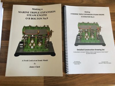
My book and drawings arrived from E and J Winter in OZ today. The delivery time was only slightly longer than some bar stock from within the UK but delivered by Evri!
I now have the original designers plans, Bertinat's tweaked design and now James Lees' version.
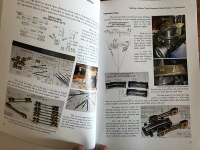
The book is a plethora of further refinements to the original design, so I plan to cherry pick what details appeal to me the most from all three versions.
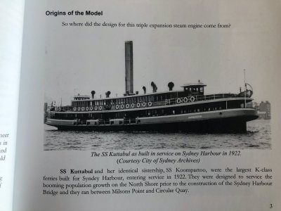
A small selection of pics just to give you an idea without getting into copyright bother. The book does mention the vessel that used the full size engine this model is based on


Bolton part eight
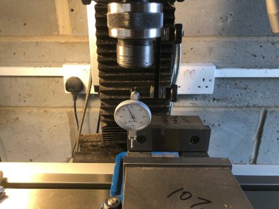
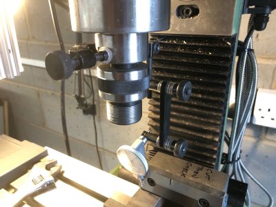
After cleaning the mill down I set the vice square to the table. This is set true using a quill mounted dial indicator. The objective is to ensure the reading does nor change as the table is moved on the X axis.
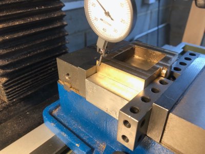
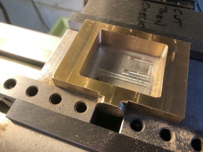
I fitted the low pressure valve chest in the vice with a sacrificial aluminium block underneath and used two 123 blocks to prevent the vice from bending the casting had I just pushed on the central boss.
I ran the indicator on the side of the casting to check I had machined it square. I had a 1 Thou of an inch run out which I deem acceptable.
Using the edge finder and the centre function on my DRO I was able to locate the centreline of the casting in both height and width (ignoring the boss). This then enabled me to mill the inside faces of the chest to size using some calculated coordinates. As I used just a 5mm cutter, I limited each cut to 5 Thou max to avoid damaging the cutter.
Next job will be to drill the holes for the mounting studs. As a side note, if I switch the DRO off I am not guaranteed it remembers it's position as I found out. I now leave it switched on and the table parked at zero zero incase of power failure.


Bolton part nine
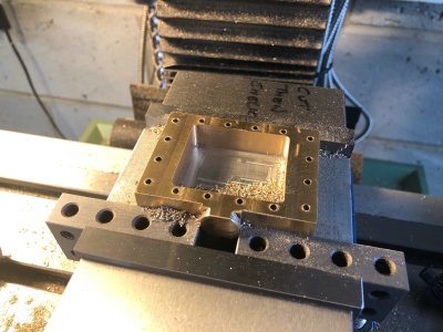
Using the DRO I drilled the through holes that take the studs that clamp valve cover and chest to the cylinder block.
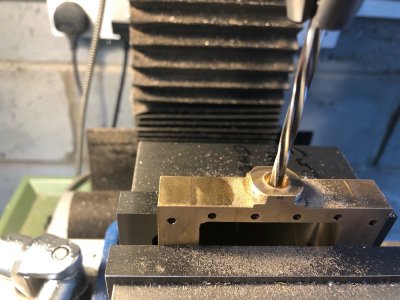
The casting was then clamped vertically in the vice. Again using an edge finder and centre function on the DRO I was able to accurately locate the hole for the valve rod and gland.
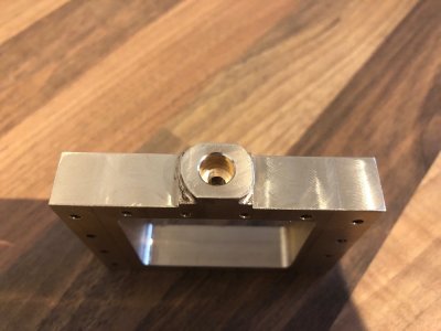
The hole for the rod was drilled undersize at 9/64" and then counterbored tapping size for a 5/32 x 32 TPI to a depth of 6mm measuring using the Quills digital depth gauge.
Finally the 9/64 hole was then finished using a 5/32" Reamer to obtain a smooth bearing finish.
The counterbored hole will be tapped after the piece goes into the lathe to turn and finish the outer diameter of the boss.
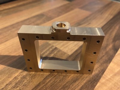


Given the precision with which you are executing this, it must be an illusion caused by perspective, but it looks like the holes on the valve side and the opposite side are not perfectly aligned. Would that cause a problem later?Bolton part nine
Using the DRO I drilled the through holes that take the studs that clamp valve cover and chest to the cylinder block.
The casting was then clamped vertically in the vice. Again using an edge finder and centre function on the DRO I was able to accurately locate the hole for the valve rod and gland.
The hole for the rod was drilled undersize at 9/64" and then counterbored tapping size for a 5/32 x 32 TPI to a depth of 6mm measuring using the Quills digital depth gauge.
Finally the 9/64 hole was then finished using a 5/32" Reamer to obtain a smooth bearing finish.
The counterbored hole will be tapped after the piece goes into the lathe to turn and finish the outer diameter of the boss.
Funny what the camera does. I looked at the part again after posting these pics as things do look off in certain aspects, mainly the valve rod hole does not look in the middle but when you eyeball everything square on, there are no visible discrepancies to the naked eye.Given the precision with which you are executing this, it must be an illusion caused by perspective, but it looks like the holes on the valve side and the opposite side are not perfectly aligned. Would that cause a problem later?
The top and bottom row of holes are designed to be in the middle of the castings but I changed this to have all fixings a consistent distance from the edge.
If the stud holes are not true then yes it would cause assembly issues and would require opening out. These were carefully peck drilled to avoid the drill drifting out of square.


