• Win a Free Custom Engraved Brass Coin!!!
    As a way to introduce our brass coins to the community, we will raffle off a free coin during the month of August. Follow link ABOVE for instructions for entering.

O.B. Bolton Marine Triple Expansion Steam Engine using castings by AJ Reeves, drawings by John Bertinat

Bolton part ten

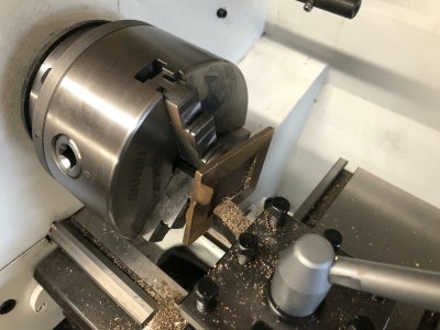
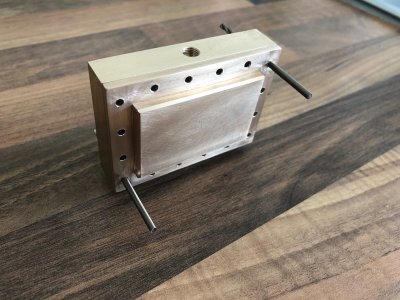
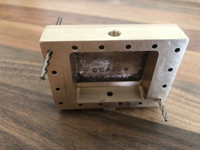
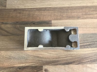
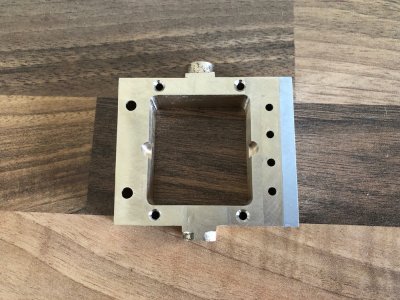
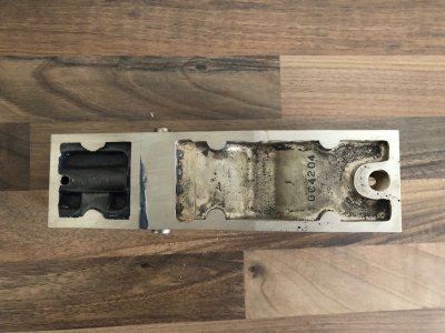
I centred the valve chest in the 4 jaw chuck on the lathe and turned the boss to shape. Note the Aluminium packing required due to the square void in the middle of the chest
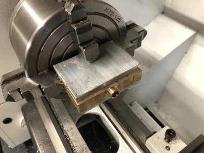
IMG_2873.jpg

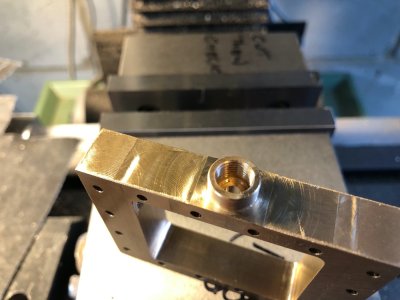
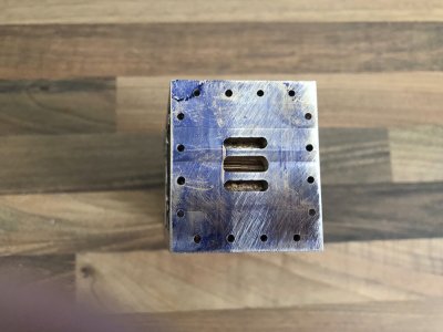
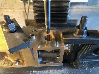
The chest was then returned to the mill vice to tap the gland boss
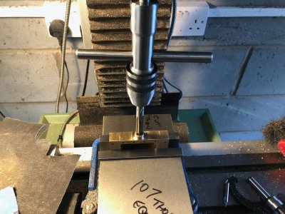
IMG_2874.jpgIMG_2875.jpg

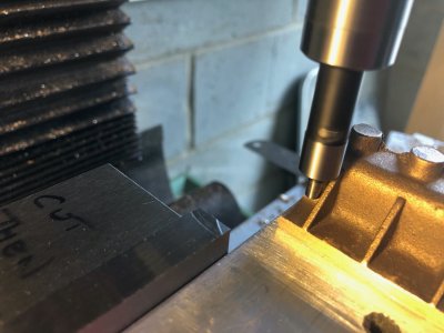
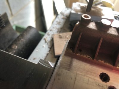
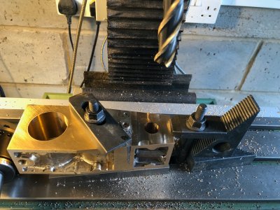
Using the same centring process the hole was drilled and tapped for the valve rod tail guide.
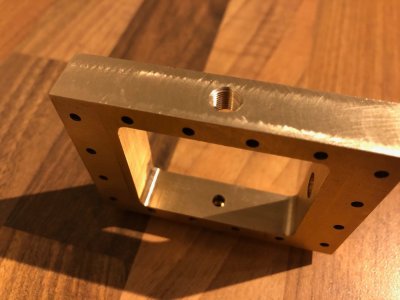
IMG_2877.jpg

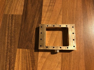
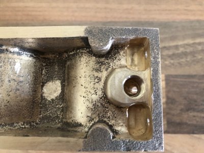
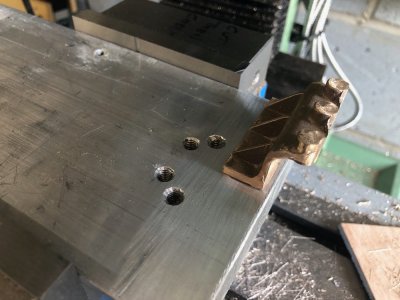
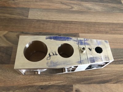
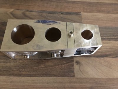
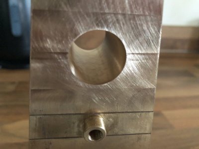
And finally the steam inlet hole and tapped holes to take the pipe flange fixings added.
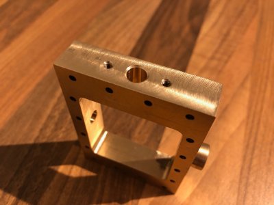
IMG_2878.jpg

This concludes the work on this chest for now. I have tapped holes to add later to carry a valve guide bracket and a take off port for a pressure gauge. I intended to add pressure gauges to each cylinder valve chest before I obtained Lees' book, having first seen them on a fine example of this engine built by Brian Newbound. I have the drawings of how James did the cross drilling for this take off but Brian did his slightly differently so I am pondering options.It is an easy job but I want to ensure I am happy with the aesthetics of my chosen method.

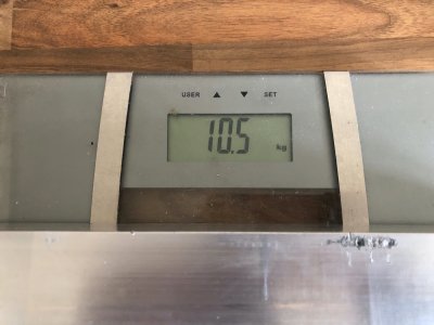
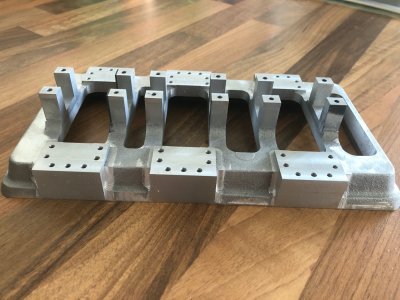
I received the chunk of Aluminium today to mill the Engine base along with integral Thrust block. mounting. This is a 400mm long billet of 6" x 2.5" T6. As you can see it isn't light. There is a mountain of material to remove and the finished piece will probably weigh between 1 and 2 kg.

.
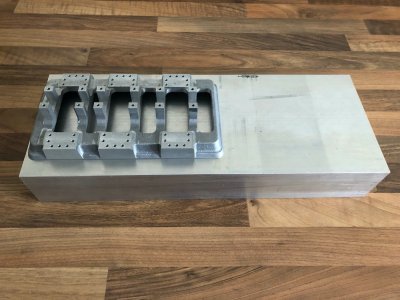
IMG_2871.jpg

IMG_2872.jpg

IMG_2876.jpg
 
Bolton part eleven

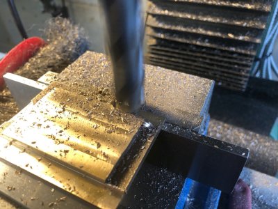
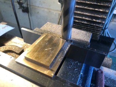
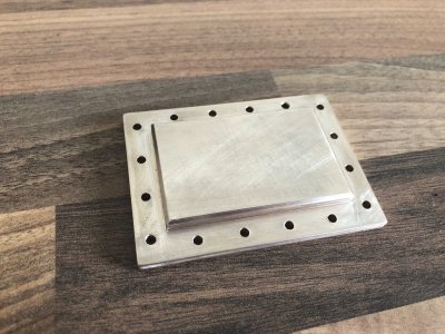
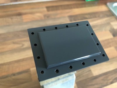
I have machined the cover for the Low pressure valve chest.
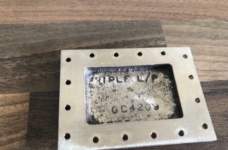
The casting was first turned on the lathe with the cast in spigot clamped in the chuck. This enabled me to machine the mating face and all subsequent work could then be carried out on the mill. The cast recess inside the chest is left unmachined. No need to do any work on this as it is more or less the same size as the drawing and serves no real purpose other than to save casting material.

The chamfer was actually milled using a six flute DIY countersink bit as I do not have a proper milling cutter for this.

The cover is actually complete and fully fettled ready for paint.

All the holes line up perfectly with the chest and all sides are flush around the perimeter.

IMG_2889.jpgIMG_2890.jpgIMG_2891.jpgIMG_2892.jpgIMG_2893.jpgIMG_2894.jpgIMG_2895.jpg
 
Nigel, this type of work is way above my pay grade but absolutely fascinates me to no end. I find myself hoping to see a new post from your metal shop every time I log into SOS. Thanks for sharing.
 
Nigel, this type of work is way above my pay grade but absolutely fascinates me to no end. I find myself hoping to see a new post from your metal shop every time I log into SOS. Thanks for sharing.

Thankyou so much Daniel, I was actually unsure anyone would be interested in this sort of build.

Posts will be pretty quick coming on this build, it is a very different pace to ship model building.The author of the book I recently purchased actually built his example in ten months. At the moment I can manage an hour a day after work and then a few hours a day at the weekend.We will see how I get on.....
 
Bolton part twelve

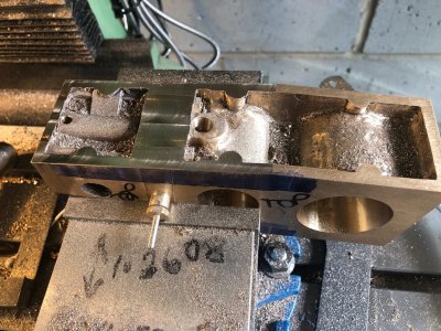
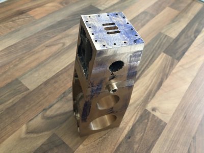
After milling the parallel sides to the block, I milled pockets to take the heads of the fixings that hold the two sections of cylinder block together

IMG_2896.jpgIMG_2897.jpgIMG_2898.jpg


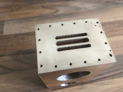
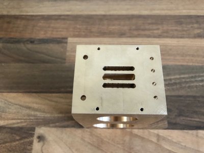
I then milled the blind slots that will become the steam ports and drilled and tapped the holes in the LP end of the Cylinder block

IMG_2899.jpg

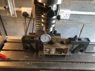
The cylinder block was then set up on the mill using a dial indicator to ensure it was true to the table

IMG_2900.jpg

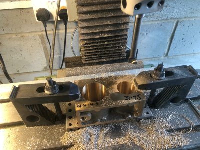
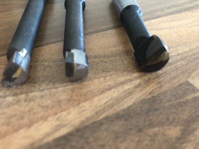
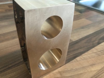
The Cylinder was then bored using a boring head. This was an Amazon special and the Brazed carbide cutters just rubbed on the Gunmetal. I extensively reprofiled these and now they cut like a dream.
The two cutters on the left have been reworked, one on the right, out of the box.

IMG_2901.jpgIMG_2902.jpgIMG_2903.jpg

The block was then drilled and tapped for the exhaust fitting and the port carefully pierced through and profiled to run through into the middle slot previously cut.

IMG_2904.jpg
 
Bolton part 13

I turned my attention to the opposite end of the large cylinder block.

The steam port channels were machined in the port face along with drilling a tapping where necessary, the stud holes.
The outlet has been drilled and tapped and the exhaust passage added.

IMG_2909.jpgIMG_2910.jpg

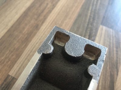
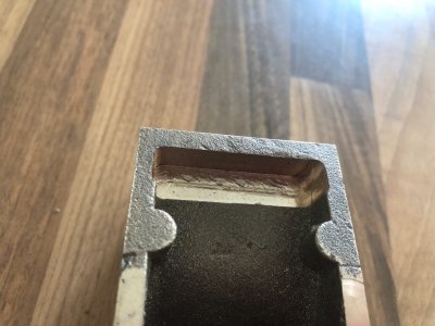
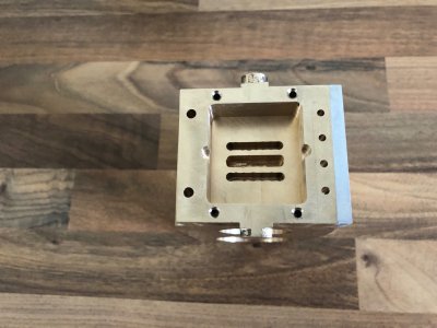
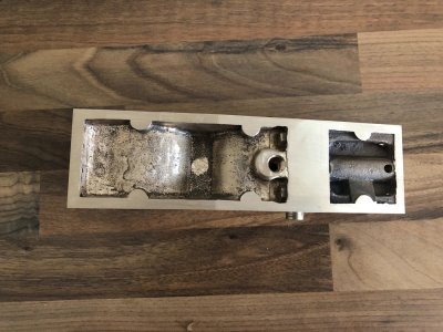
The intermediate valve chest hs had it's drillings added and the inside faces milled. The two Scallops are to allow steam to enter from the internal passages in the high pressure block

IMG_2911.jpgIMG_2912-1.jpg

I have decided that as each piece is complete and needs no further work, it will be painted. Using digital readouts for machining does away with the multiple trial assemblies and using items as drilling templates with probably the exception of the cylinder covers. This is a huge timesaver plus paint as I go means I am not faced with a full strip down at the end of the build. There are just shy of 500 fasteners on this engine!

Now I want to do something different. I have seen this engine in every shade of green and one in Crimson. I have chosen gloss grey, I feel the contrast with this and the polished brass and steel will look quite good.My inspiration is the fabulous model steam engines that used to be made by Martin,Howes and Bayliss.

I have sprayed the cover in this shade after first priming with Acid etch primer.Paint will be cleaned from inside the holes and the gasket face polished once the paint is fully cured.I photographed this three times and each time new specks of dust appeared so gave up trying to get it dust free. Any specks are sat on top, not in the paint finish.

IMG_2913.jpg
 
Nigel, what do you anticipate the highest cylinder pressures will be?

Hi Daniel

The limit will be 60psi which is the working pressure of the boiler I plan on running it on, the engine would cope with more but the goal is to build the model so it will run as slow as possible. I would like to try and get the revs down to 120rpm which means lower pressure.There is a larger Stuart single cylinder engine on YouTube running at 5rpm! However Steam does not scale so there is only so far you can go getting the engine to run at scale speed.
In James Clarke’s book he mentions 120rpm at 15 psi. He had made substantial changes to Bertinat’s valve gear design. Some changes I get like the timing however he has increased valve lift on the last two cylinders. That I do not understand. Port opening is limited by port spacing in a slide valve engine. He has not changed port sizes or spacing so the extra lift accomplishes nothing imho.
This is partly why I am holding back making the crankshaft, I need to fully understand the timing choices. Stuart stipulate different valve advance on their triple expansion engine similar to James Clark but Bertinat has advance the same for all three cylinders. I may even purchase Stuart’s plans for their version to see how they do it. I am still planning on turning the eccentrics on the crank so I only have one go at it with no adjustment.
 
However Steam does not scale
Now that's an interesting fact I had never considered. Back in the 1980's I was the project manager of a crew building a cogeneration foundation inside an existing refinery here in Texas City, Texas. We were working in the steam generation section of the refinery next to 3 gigantic boilers. One day one of boilers became over pressurized and actuated the pressure relief valve sending a banshee screaming column of steam over a hundred feet in the air which of course made all of us in our crew almost mess ourselves.
 
Scary stuff. On the prototype of this engine and depicted in some model builds is a series if radial grooves in the cylinder caps. These are to allow the cap to disintegrate if the safety valve fails. The intention is direct the blast upwards rather than a cylinder failing.
I have found a period cutaway drawing of the vessel carrying this engine. Frightening thought is the passenger deck is directly above !!!
 
Bolton part fourteen

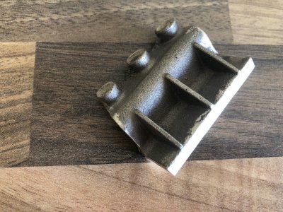
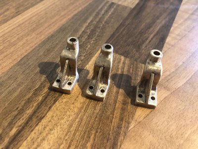
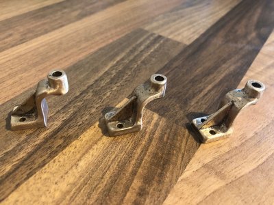
As I am waiting for some tooling to arrive, I proceeded to make the valve rod lower support brackets today. There are three in total and they are bolted to the underside of each valve chest. There are all identical with the bolt holes and valve rod hole relationship critical to ensure no binding during running.

The casting kit includes these as one single casting which I will work on as far as is practical before splitting into three.

The casting as supplied after a quick file to remove flash

IMG_2914.jpg

The casting clamped in the mill and the bolted flange face and back edge lightly milled to true up

IMG_2915.jpgIMG_2916.jpg

The casting is turned around and the face of the bosses very lightly skimmed to provide a good reference for my edge finder

IMG_2917.jpg

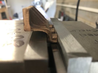
The piece is then glue square and flat down to my ever dwindling chunk of Aluminium using medium CA. This mocks up how the brackets are bolted to the engine.

IMG_2918.jpg

The edge finder and DRO centre function are used to establish centre in relation to the gussets. There are fractions of a mm clearance between gusset and the nuts so these have to be my point of reference, not the bosses.

IMG_2919.jpg

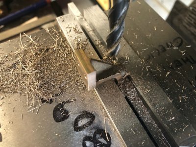
With the datum centres established, the mounting stud holes were drilled and the hole to take the valve rod drilled then reamed to size.

IMG_2920.jpg

This entire process was then repeated on the remaining two brackets referencing each one from scratch to ensure accuracy. The valve holes are not all central to the bosses as the casting isn't that accurate. Visually after fettling and painting this will be less noticeable.

IMG_2921.jpg

The item is unbonded by heating with a blowtorch
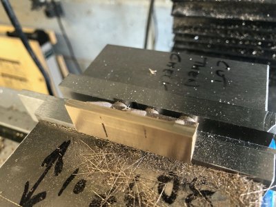
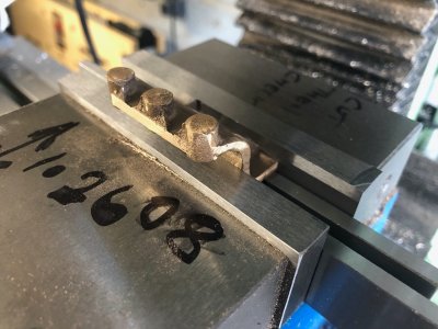
After cutting the piece into three I machined each bracket to length with the mill. The tapered top will be done simply with a Proxxon sanding disc in the Dremel.
Yes this set up is sketchy, so VERY light cuts to prevent the piece flying across the workshop

IMG_2922.jpg

The completed brackets after hand fettling and ready for paint. All open corners are radiused to make the items look like individual castings as they would be on the prototype

IMG_2923.jpgIMG_2924.jpg
 
Last edited:
Bolton part fifteen

As I have had this last week as holiday, I have made good progress, sadly back to work tomorrow:(

I bolted the two cylinder blocks together including the sandwiched Intermediate pressure valve chest and gaskets.. This enabled me to add the steam ports and drillings to the high pressure cylinder then mill the tapered sides to the assembly.

The supplied castings are criticised for inadequate material on the sides of the intermediate valve chest and mine is no different. This area is visible as the JB weld on the side that was used to hold my temporary aluminium reference piece. This will need a little more JB adding. This would have been much worse had I not removed extra material for the 0.9mm steel cladding.

IMG_2927.jpgIMG_2928.jpgIMG_2929.jpgIMG_2930.jpgIMG_2931.jpgIMG_2932.jpg
 
Bolton part sixteen.

I set the cylinder assembly up on the mill table and after a lot of "dialling in" I was happy with the alignment and that the existing bores were properly referenced on the DRO.

Before using the boring head on the high pressure cylinder, I opened the hole up with a long 18mm milling cutter used in plunge mode. This did a satisfactory job of getting a clean initial hole big enough to take the boring bar.

The cylinder bore was then taken up to size using the boring bar and head.

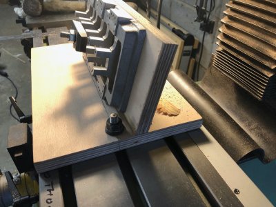
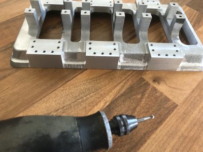
As the vice was currently dismounted from the mill, I was keen to try out a milling fixture I had built from plywood. This was designed so I could mill the sides of the "pillar features" on the base casting to match the footprint of the columns that sit above.It angles the base so that the bottom of the mill cutter follows the sloping sides. Any remaining material will simply be removed with a carbide burr in my Dremel.

I had looked at adjustable angle tables but aside from not being big enough, they would put the base outside the footprint of the mill table and cutter.

IMG_2933.jpgIMG_2935.jpgIMG_2936.jpgIMG_2937.jpgIMG_2938.jpgIMG_2939.jpg
 
Hi All

This is a departure from my previous builds and a venture into model engineering. Some may say this is a leap into the extreme, akin to building a fully framed ship as your first model.
Yes, this is probably one of the most complex marine steam engine models available in castings.
I am not a complete rookie, I was trained in machining and bench fitting way back in college plus I have worked in engineering for the last 36 years.

On to the subject, I believe Bolton's design is based on an Australian Ferry engine. The engine incorporates an integral Condenser, an air pump and two water pumps.The three pumps are mechanically driven by the engine itself.

For those unfamiliar with steam engines, the triple expansion design reuses steam twice to maximise efficiency.Steam enters the small volume high pressure cylinder. The exhaust steam from this cylinder then passes to the Intermediate pressure cylinder. The exhaust steam from this cylinder then passes to the largest, Low pressure cylinder. The exhaust gasses from this last cylinder are "pulled" out by the vacuum created by the Air pump and into the condenser.The condenser has a water jacket to help cool the steam which is circulated by one of the water pumps.The second water pump is used to keep the Boiler replenished with water.

The model will work as the prototype on live steam. Along with the obvious machining of the engine itself, there is a plethora of valves plus a copper tube matrix to build inside the Condenser.

This project is one of three "Bucket list" projects that I would like to finish before my time is up. My Imara build with two Steam Engines is the first, this is the second. I have found a copy of a book covering the build of the third. Similar price second hand as one of Bordroit's Monographs but worth it given the detail of the model covered.

I have reached the end of what I can tolerate with my cheap 7 x 12 mini lathe. It simply cannot do what I am now asking of it. With that in mind, I have ordered a 10 inch swing 22 inch between centres medium size lathe with stand and digital readout, that is being delivered on Wednesday along with an engine crane on hire to lift and install the thing.

Enough waffle, time for some picturesROTF

Some snaps from the drawings showing the general arrangement. The model will be 10 inches long when complete and weigh roughly 22lbs

View attachment 531505View attachment 531496View attachment 531497

Now the castings.These obviously all require extensive cleaning up and machining. Everything os cast in Gunmetal apart from the base, which is aluminium.

The two cylinder blocks, three valve chests and two valve chest covers. The block is split into two and will bolt together sandwiching the Intermediate pressure valve chest.

View attachment 531498

The aluminium baseplate which houses the main bearings and crankshaft. The six supporting columns, two of which include the condenser casing. The condenser end caps are also shown

View attachment 531499

The top and bottom cylinder covers and the two piece pistons. The round lugs are designed to be used for initial chuck holding in the lathe and are removed during the later machining stages. Time will tell how useful these are.

View attachment 531500

The straps for the eccentrics (used to control the valves), the big end bearings, valve blanks and buckles and finally gunmetal bar to make the main bearings.

View attachment 531501

Finally, the casings for air pump, water pumps, valve rod guides and steam Globe valve.

In addition, numerous sizes of steel bar stock, bronze bar stock plus @ 500 fixings will need to be purchased to build the model

View attachment 531507
i have always been fascinated by the triple expansion engine. it was the zenith of that technology.thanks for sharing
 
Bolton part seventeen

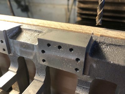
A pic heavy update. I finished squaring the "columns" on the side of the base and the second pic illustrates some shaping work carried out with a carbide burr. I keep dropping on to this item and doing it in stages as my cordless Dremel's battery only lasts so long before it needs charging.

IMG_2940.jpgIMG_2941.jpg


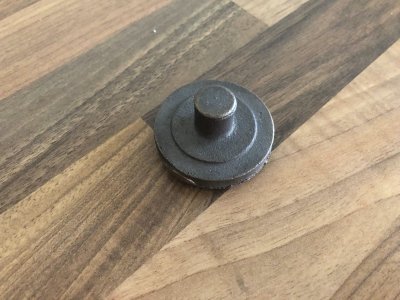
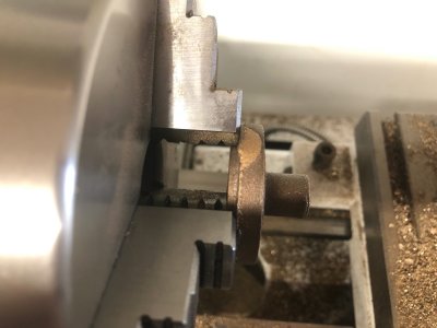
I then turned my attention to turning the castings for the cylinder caps. The two photos show the raw casting for the High pressure cylinder. Note the long "chucking" spigot cast onto the top

IMG_2942.jpgIMG_2943.jpg

The piece was clamped into the lathe chuck gripping on the ledge of the bottom of the casting. This ledge forms a register that will engage into the top of the cylinder's bore

IMG_2944.jpg

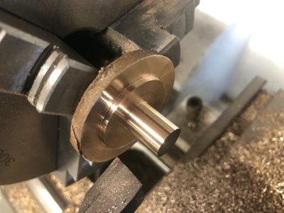
The spigot and top faces were turned to size. The bottom of the spigot will remain as a shoulder that a pressure relief valve will screw up to

IMG_2945.jpg

Finally job is to add the chamfer to the step using the compound slide for the angle

IMG_2946.jpg

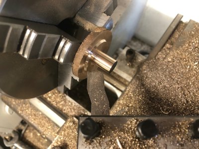
The workpiece is then reversed in the chuck which is now gripping the spigot. The underside is then turned taking great care to ensure the register is a good but not tight fit in the bore. I turned this down 1 thou at a time, constantly checking the fit in the block.

IMG_2947.jpg

The item is then drilled and tapped right through for the pressure relief valve


IMG_2948.jpg

The item was turned around in the chuck again to remove the spigot leaving the valve boss.Sorry Folks forgot to take a picture of this.

I repeated these step with the other two covers and now I have a full set of three, The LP and IP covers touch which is right to the drawing, not so good if I paint these as intended. There is no clearance for paint! If I do paint these, small flats will need milling for paint clearance where they meet.

IMG_2949.jpg
 
Back
Top