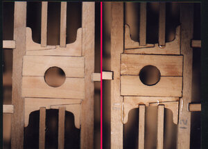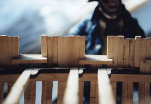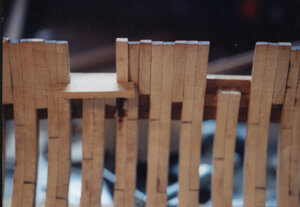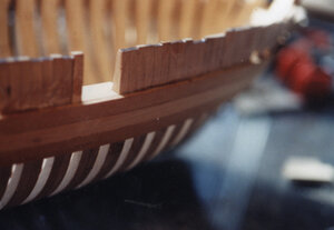
Oneida war of 1812 brig

image48.JPG
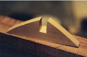
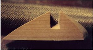
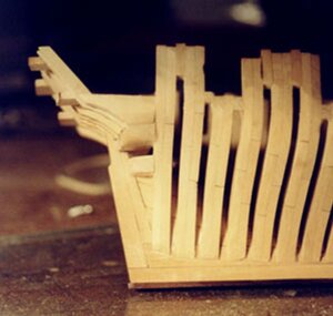
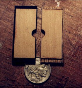
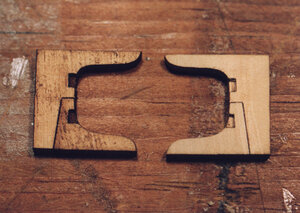
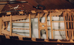
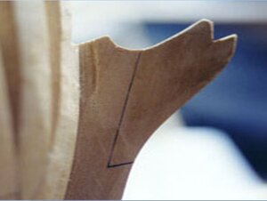
Now that the upper transom and the stern timber assembly is finished it will be set aside and the lower transom will be shaped and put into place. Its rough shape is a triangle with a notch cut in the center. The bottom of the notch has to be cut on an angle in order to set against the stern post.

Sometimes this area is filled in solid sometimes more than one lower transom is used. We will never know how exactly the Oneida was built so i used one lower transom. This has to be fit before the upper wing transom is put in place


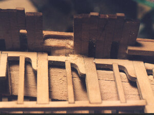
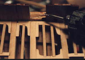
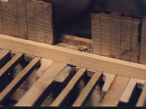
image49.JPGimage50.JPGimage52.JPG
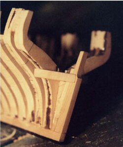
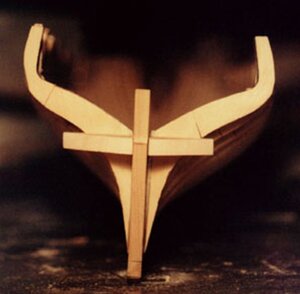
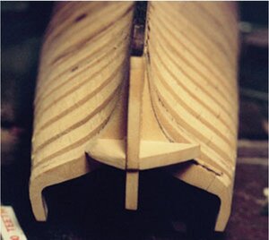
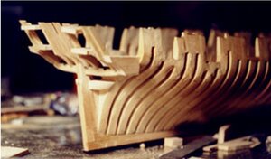
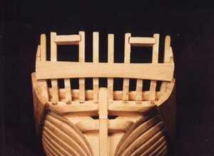
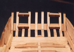
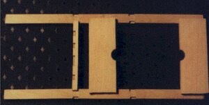
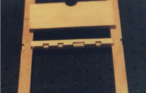
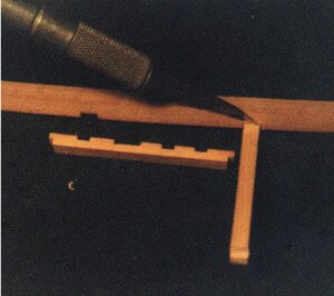
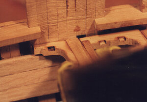
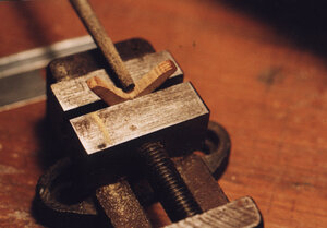
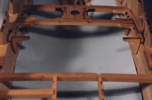
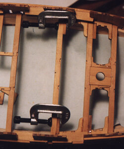
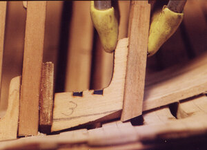
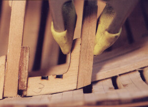
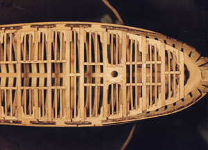
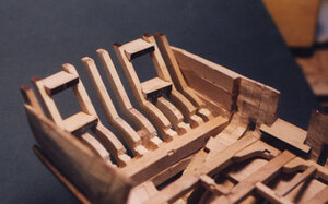
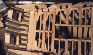
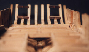
Three views show where and how the lower transom fits in the hull. The transom sits on top of the deadwood and is notched around the inner stern post. At this point the piece is quite large and will have to be cut down to match the shape of the hull.


image51.JPG
image53.JPG
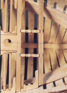
Here we see the transom taking on its final shape. The piece is sanded then fit to the hull and removed and sanded some more until it has a close, but not finished shape. The final shape will be done when the hull is sanded to shape.
 
image54.JPG
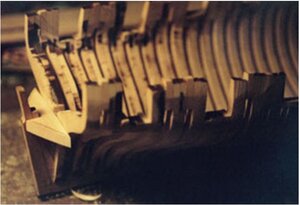
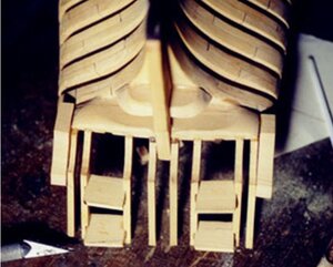
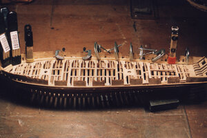
With the upper and lower transoms in place and partly shaped to the contours of the hull, stern blocks are added. These blocks are glued to the outer edge of the last stern timber and to the face of the last frame. In the pictures they look very large and out of place, however a majority of the block will be ground away when the stern is given its final shaping. These lower blocks are quite an important piece, as the ends of the thick wales will be fastened to them.

image55.JPGimage56.JPG
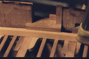
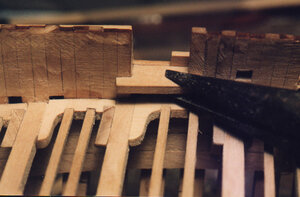
Here the lower blocks are given a rough shaping. The upper edge of the stern block also acts as a platform for the outer stern timbers. If the ship has a quarter gallery it would be built off these blocks, a door way would be framed in the space above the block between the stern timber and the last frame. In the case of a quarter badge a window is framed in this space
 
image57.JPG
image58.JPG

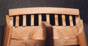
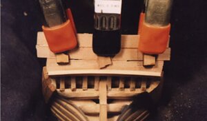
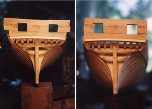
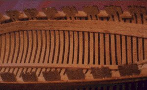
Starting with a wide plank an arc was cut along the lower edge where the arched lower molding will fit. The plank was glued as one piece right over the gun ports. Photos show an outer and inner view of this plank


image59.JPG
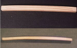
Trying to bend a piece of wood for the arched molding i find it easier to cut the arch.
From a 1/4 thick piece of sheet stock a blank was cut a little longer than the width of the stern and about 1/2 wide. Along the edge the arc is marked out and cut. A spindle sander or a sanding drum on a Dremel can be used to sand the arc. The lower molding piece arcs in two directions making it vertically impossible to bend in both directions. Fabricating the molding by cutting the arches is the more practical way of making it. Starting with the upper edge sand the arch until you have a nice tight fit against the lower edge of the stern plank. Once you have a nice fit cut the lower edge of the arch until the molding is reduced in thickness to 1/8 inch. At this point you will have an arched molding piece 1/2 wide and 1/8 thick.


image60.JPG


Looking at the stern from the bottom the arch of the lower molding can be seen. The lower molding sits against the lower part of the stern timbers and tight against the stern planking. This molding serves as the finished edge between the stern planking and the lower transom planking. Finishing the edge of the molding is left up to the builder. It can be left as a square edge or rounded to form a bull nose. On war ships of this period the molding was given a fancy molded edge.


image61.JPG

There is a gap between the plank because they are being test fit. Everything will be given a tight clean fit between planks for the final fitting.

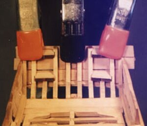
The rest of the stern planking is glued to the stern timbers in one long piece. This was done so the planks will take a smooth bend. The planks also ran over the gun ports, they will be cut out later. I found by cutting short planks between the ports and on either side did not result in a continuous smooth bend of each short plank. The shorter planks were also more difficult to bend. On the prototype three wide planks were used for the stern. At the scale of the model the planks would have been 19 inches wide. Its possible planking that wide could have been used, but in actual practice narrower planking about 8 to 10 inches wide would have been used. Small pieces of wood are used to apply an even pressure from the clamps over the entire width of the planking. The small wood pieces also aids in keeping the planks even with each other.
The curve of the stern was slight so there was no need to soak the planks they bent dry with no problem.


image62.JPG
Here is an inside view of the stern. You can see the seam where the planking meets the lower molding. This plank was cut to fit the arc of the molding from side to side. It would not be wise to try and bend the lower plank in two directions at once, one to match the molding and one to to the curve of the sterm. The planks did conform nicely to the slight arc of the stern. At this point the planking is left longer than the stern.


image63.JPG
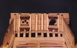
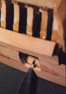
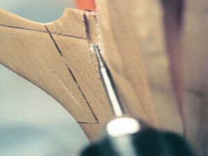
To cut out the gun ports, holes were drilled to give a starting point for cutting the ports. There are several ways to remove the bulk of the wood, either use a Dremel with cutting burs or a fine scroll saw blade.


image64.JPG
As the cutting gets close to the sides of the ports an exacto blade was used to make a clean sharp edge.
 
Dave, I do hope you continue with this as I plan on the Oneida as my next project after my Halifax can this be done successfully without the use of a jig

Best
Ed
 
over the years a lot of builders did successfully build the model without using a jig.
The prototype model i built, the one in this log, worked out just fine.

i built the frames freehand but it would be a little more accurate using the frame drawings by placing a piece of clear mylar over the drawing so glue does not stick to the paper drawing, sticking pins along the edge of the frame and use that as a guide to assemble the frames. By constant checking that the frames are level side to side and they do not lean back or forward will insure the hull will come out right.
there are a bunch of videos on plank on frame building. They are the Caustic and General Hunter not the same ships but the building techniques are pretty much the same.


Dear Dave
you are doing excellent work, I'm learning allot from years explanation & Pictures that Attached them.
tank's
 
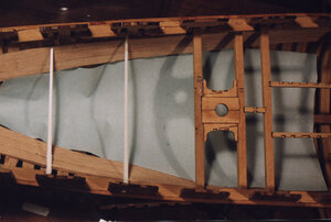
As i look through the original build i did not find anything on installing the deck clamps. But that is the next step after the hull has been built and sanded inside and out. The light blue line is the deck line under that line you see the beams which sit on the clamp. This is a critical part of the build because the location of the clamps sets the height of the deck, and the gunport sills and the final height of the bulwarks and finely the caprail. No pressure here there is a little lee way and some adjustments can be made, but it is best to be as close as you can. Installing them is easy because you do not have the deck in the way so you can clamp them tight to the hull.


1598036482538.png
 
BUILDING THE DECK

i build all my decks in sections because i found out through trial and error if you start at one end and build in one direction slight errors accumulate so by the time you reached the other end you may be long or short. The mast partner beams may or may not fall where they should. or hatches may not fall exactly where they show on the plans.

Getting started


image66.JPG
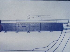
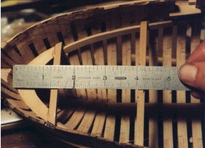
The deck will be built in sections, first location will be at the forward mast, then the capstan base and finally at the location of the second mast. first take the location of beam four off the plans. It measures four inches back from the inside of the apron.


image67.JPG

Deck beams are longer and thgey have to be cut to fit the hull so
Deck beams four and five are cut to length and fit to the hull. Here beam four is set back from the apron four inches.


image68.JPG

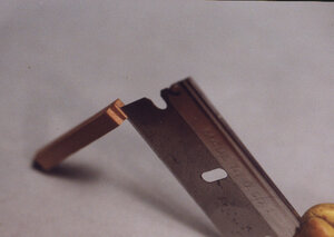
Mast partners and knees are assembled to the beams out side the hull. The knees at the ends of the beams are only set in place to keep the assembly square they are not glued to the beams. This is because they will be slid inward or out to rest against the hull once the assemble is installed.


image69.JPG
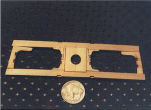
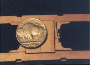
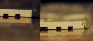
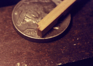
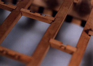
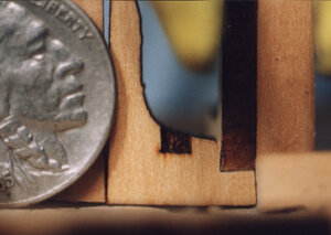
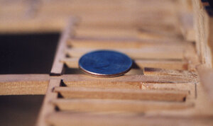
Looking very close to the assembled section you can see a slight out of alignment of the pieces. Where the mast partners are above the beam is about the same as the outer rim of the nickel. This demonstrates the actual building is within about .003 thousandths of an inch. At this stage of the build it is of no concern because once the deck has been completely built it will be sanded and all parts will be smooth and level.
 
the grainy old photos and low res scans are not the best and not nearly as clear as digital imaging of today. This project was done in the days of film cameras.


image70.JPG
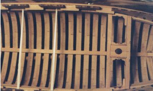
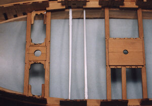
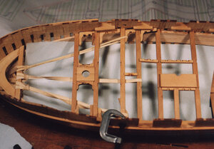
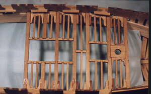
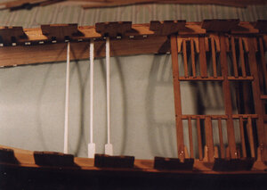
When the assembly is finished it is set into the hull in its proper location on top of the clamps. The only pieces that are not glued are the knees at the end, these will be fit later. From here I jumped to the capstan base between beams 8 and 9. All the beams have to be trimmed to fit into the hull. The two white sticks are McDonald coffee stir sticks at the location of beams 8 and 9. Cut the ends of the stir stick with wire cutters until they fit the hull from side to side. When you have the right size mark the center of the sticks and the center of the beams. Mark and cut off the ends of the beams. You can build the deck starting from beam 1 and working your way to the stern placing each beam in order. I built the three sections at the forward mast , the capstan and the second mast and placed them in their exact locations. If any adjusting has to be done to the deck it will be done in between these set locations.


image82.JPG
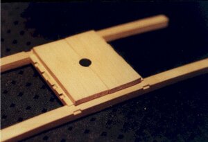
Unlike the mast partners which set flush with the top of the deck beams, the capstan base sits notched above the beams. This is how the finished section looks. Now taking it apart piece by piece you can see how it was built.

image83.JPG
To begin the black char was scraped off the notches around the edge. you do not have to clean the char down to bare wood just remove enough so the wood surface peeks through.


image84.JPG
The two pieces of the capstan base were placed one at the center and the other at the end of the beams. This was done to keep the beams square and parallel so the length of the carlings can be fit nice and tight into the bean notches. spreading out the base pieces stabilized the beams.

image85.JPG
When your sure the length of the carlings fit tight in the notches, the next step is to cut a notch at the ends of the carlings so they sit flush with the top of the beam.


image86.JPG
Flip the beam upside down and with a knife mark the side of the beam on the carling.


image87.JPG
Cutting the notch at the end of the carlings is quite an easy job. Using a fine tooth razor saw cut at the line marked with the knife. Using a razor blade, chip out the wood for the notch. Don't make your cut to the final depth all at once. Keep placing the carling back into the beam notch and slice a little off at a time until the carling sits flush with the beam.
 
much better images i must of bought a better scanner or something


photo1.jpg
After beams 4 and 5 which hold the forward mast partners are in pace and beams 8 and 9 which hold the capstan base have been placed in the hull, we will now place beams 6 and 7.
The idea for building a deck in sections is any errors are confined between these two main sections and any corrections are small compared to one big correction at the final end of the deck.
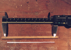
First measuring sticks are used in the location where the beams will fall. When the length of the beams are determined the measurement is transferred to the beams and they are cut to length.


photo2.jpg
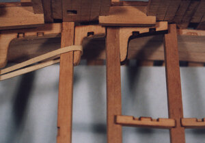
The three lodging knees are temporarily put into place between the beams to check fit. Rubber bands were used to hold the beams and knees in place. Notice the last knee on the right it does not fit in the space and has a slight overlap on to the beam. That is the creeping error and by the time i would reach the stern everything would be off. Now i can remove just a little off each knee and get this section fitting in place.


photo3.jpg
Taking a close look it is apparent beams 6 and 7 plus the 3 knees are slightly to large to fit the area between beams 5 and 8. Not all the extra material was taken off one knee, this may result in the carlings not fitting properly. Just a little was taken off each knee until the beams and knees fit in the allotted space.


photo4.jpg
The each knee was clamped in a vice and the notch for the hanging knee is cut out using a fine tooth razor saw.


photo5.jpg

When the knee is cleaned of the laser soot and the hanging knee notch is cut, the lodging knee is glued in place.


photo6.jpg
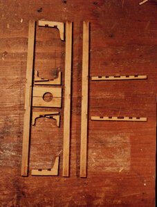
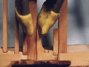
To clean the soot off the knees they are placed in a vice. Once held in place a file is used to remove the majority of the soot. A little touch up with sand paper and finally a little scraping with a razor blade or Exacto knife will finish the knee.


photo7.jpg
Here is a view of the hanging and lodging knees in place and ready for deck beam 6.


photo8.jpg
photo9.jpg
photo10.jpg
Deck beam number 6 is cleaned up on all four sides and placed in the hull. Small C clamps are used to hold the beam tight to the side of the hanging knee. Before the final placement of the beam lay all the carlings in place. This is done to insure the carlings will sit square to the beams. The deck clamps are wide enough to allow a little play in moving the beams from side to side. When trimming the beams to fit the hull allow a little side to side movement for minor adjustments in lining up the carlings.


Note: ships built during the war of 1812 did not have hanging knees, they were built fast and under the pressure of getting ships on the lakes. The Oneida was built before the war and Henry Eckford was in no rush to get the ship afloat. Hanging knees were a part of deck construction so it is possible they were used.
 
Last edited:
in the original laser cut parts the Notches were laser etched, that is why you see a slight laser char in them. This idea did not work out so well because the deck would have to be built perfect in order for all the pre cut notches to line up.

photo1.jpg
The carlings were cut slightly over size to allow for a tight fit and any slight adjusting of the deck beams. There will be a slight difference in the lodging knees and the length of the carlings. The distance between each deck beam is a compromise between the lengths of the lodging knee and the carling. If the knee is to long it will spread the distance between the beams and the carling will be to short to fit in the notches. Or the other way around if the carling is a bit to long it will cause the beams to be to far apart an the knee will not fit tight. When you are setting the beams check to be sure the knees and carlings will both fit tight or at least one or the other can be trimmed to fit. Here we can see that when the knee between beams 5 and 6 were fit, it resulted in the beams being a little closer. The carling can now be cut to fit. Don’t take all the extra off one end or the notches for the ledges will not line up between the carling and the knee. Remove a little material off each end until the carling drops into the notches.


photo2.jpg

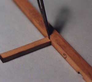
Once the carling is cut to the correct length the notch is marked. All the notches in the beams and carlings are cut exactly the same size. Using any beam, flip it over and set the carling in the notch. Using a scalpel or exacto knife score the under side of the carling.


photo3.jpg

With a fine tooth razor saw cut along the score line to a depth of about one half the thickness of the carling.


photo4.jpg

When making notches in carlings and ledges sometimes more than one can be clamped in a small vice and cut at once. This works when a pair of carlings, which fit between beams, need to be exactly the same.


photo5.jpgphoto6.jpgphoto7.jpgphoto8.jpg

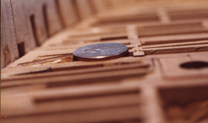
The depth of the notch is a matter of trimming and fitting until the carling sits flush to the top of the deck beam. In photo 5 a razor blade is used and a cut is made horizontal from the end. Photo 6 shows the cut piece is cut out from the notch. With practice you will be able to judge the exact depth of the notch. Photo 7 shows slices are cut from the notch until the carling falls into the deck beam notch. In photo 8 it is shown the slices are very thin when compared to the raised rim of a nickel. Trimming the length and trimming the notch the carling finally sits into its deck beam notches


photo9.jpg
All the carlings are trimmed, notched and fit in their proper place. If any carlings are out of square use the shortest carling to correct the problem. In the case of the section we are working on it would be the short carling between beams 6 and 7. Shift the beams right or left and average out the carlings over the area from beam 5 to 8.


photo11.jpg
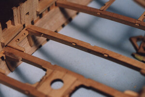
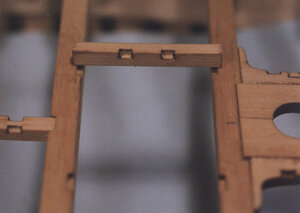
Once all the beams, knees and carlings are in place its time to fit the ledges. Ledges are smaller beams, fit between the heavy deck beams to add support to the deck structure. Ledges follow the same procedure as fitting a carling. First they are cut to the correct length, then a notch is cut in the end allowing the ledge to fall into the notch of the knee and carling.

You can see the Epoxy on the beams and knees, i don't worry about a little glue seeping up because the entire deck will get a good sanding once it is finished and the extra glue will be sanded away.
 
actually the photos got better because the other night i was searching through old CADs and found parts of the original build and i did not have to use low res images pulled down from the web.

photo1.jpg
With the deck finished back to beam number 9 we will now move towards the stern. Take a measurement from deck beam 9 to deck beam 10. This is done to locate beam number 10 in the hull so a measurement stick can be used to determine the length of the beam.


photo2.jpg
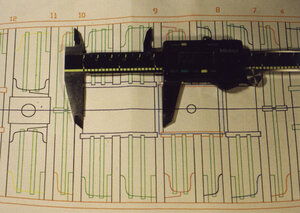
Once the location of beam 10 is set, beams 11 and 12 are also located. Measuring sticks are then used for the length of these beams. you may be wondering what is up with the measuring sticks? i used them because the Calipers would not fit down into the hull and a ruler longer then the width of the hull also will not fit down into the hull at the level of the clamps.


photo3.jpgphoto4.jpgphoto5.jpg
Remove the measuring stick for beam 10 and measure it. Take the number and divide it in half. Starting at the center of the notch measure to the end of the beam. As a final check measure the beam from mark to mark. What is going on here is working all the measurements from the center to both ends.


photo6.jpg
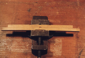
Once the beams are marked for their length they are cut down to fit the hull. You don’t want the beams to fit tight in the hull so give yourself a little play to move them back and forth to allow adjustments when squaring up the carlings. Using the center carling notch both beams are lined up and clamped in the vice.


photo7.jpgphoto8.jpg
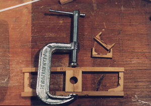
Deck beams 11 and 12 along with the mast partners and knees are assembled outside the hull. Begin by gluing the two halves of the mast partners together, then clamping them between the beams. Use the lodging knees at the ends of the beams to insure the mast partners sit square and beams 11 and 12 are parallel. Do not glue the knees in place at this time they will have to be notched for the hanging knees and adjusted to fit the hull.


photo9.jpg
Soot from the laser cutting will smear from handling the pieces. Before parts are glued into place the pieces are scrapped with a razor blade to clean them up. Glue together the two mast partner knees and clean up the soot. These knees are glued in place before the unit is placed into the hull. You can see in the photo the notches were originally laser cut, that idea did not work very well because you need to be absolutely dead on in the building process to insure all the carlings and ledged lined up.


photo10.jpgphoto11.jpg
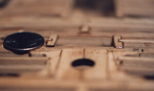
Taking a very close look at the fit between the hanging and lodging knee the fit is very tight. The gap above the nickel between the knee and the beam will close up once a clamp is applied and also pulling the seam closed between the between the notch in the lodging knee and the hanging knee.


photo12.jpg
When the mast partners and knees are glued in place the lodging knees are removed and the unit is placed in the hull. Deck beam 10 is now put in place and the carlings added. The same steps that were done with beams 6 and 7 were also done between beams 10 and 9 to check the distance for both the carlings and knees to insure both will fit snug within the space between beams. With deck beams 10, 11 and 12 in place beams 14 and 15 which support the skylight are measured out.


photo13.jpg
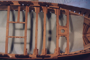
Carlings are in place from deck beam 9 to beam 15. The next step will be to install the half beams and deck beams 13, 16 and 17. Once these beams are in place the knees and ledges are placed in the deck structure.
 
final notes on building the deck


photo1.jpg
The first three lodging knees at the bow are cut over size. Everyone of them will have a slightly different shape to the hull so the knees have to be shaped to fit. First take each set of knees and shape them to fit against the hull.

photo2.jpg

The knees are cut quite a bit oversize giving plenty of room for fitting.


photo3.jpg

Fit deck beams 1,2 and 3 in place with the carlings. Then continue to cut a notch for the hanging knee and fit the lodging knees in place between the beck beams.

photo4.jpg
Here we see the deck complete from beam 4 to the breasthook around the bow.


photo5.jpg
At the stern the deck ends at the stern timbers. A notch was cut into each stern timber to seat the deck transom. Deck beam 17 sits on the wing transom. Also the last frame has to be trimmed down a bit


photo6.jpg
You will see a difference between the plans and the deck as built. The plans show two ledges between beams 16 and 17. The deck as built shows only one ledge, the reason being any differences in the deck as built were adjusted at this point. On the model the deck was a slight to long even after all the care and adjusting and i ended up just one ledge to long overall. so the last knee was cut short and one ledge was installed. The deck itself is not to long it is all the parts of the deck that were placed in the model.


photo7.jpg
Looking at the stern from deck level the deck transom is a little high at the ends because the arc of the deck was not cut in the last beam. This will be taken care of once the deck is finished sanded.

building a deck is a fussy job and requires time and patience to cut all the notches and fit all the parts. So expect to spend some time on the build.
 
Finishing the deck


photo1.jpg
The pieces making up the deck were not set exactly level. The differences are very slight as you can see compared to the dime sitting on the deck. Some hanging knees were a little above the deck beams.

photo2.jpg

Here again we see a slight difference in the carlings when they were cut to fit the notches in the deck. The difference is less than half the thickness of a dime.


photo3.jpg
The worst is a knee sticking up the thickness of a dime. The average is about the thickness of the rim on a dime as you can see the carlings and ledges to the right of the dime.


photo5.jpg
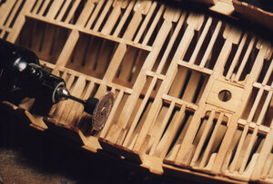
I used a home made sanding disk on my Dremel. The disks are one inch diameter plastic from bottle tops with 100 grit sandpaper glued to them. For backing I use the rubber drum sander from Dremel. These disk sanders will cut fast so be careful not to sand right through the ledges, or sand dips in the beams. A very light touch is all you need to level out the deck.


photo 5.jpg
Here is a sample of a before and after sanding. I don’t worry about getting epoxy on the surface of the deck. Epoxy sands very nice and cleans right off. The slight difference in wood color shows off the different parts of the deck. At this point you can leave the deck wide open to show off the work, or put on just a few deck planks.
 
Before moving on with the build i want to take a post to talk about building from semi-kits, timbering sets or right from scratch. These do not come with step by step instructions and as the saying goes you may find you painted yourself in a corner. Pre planning is a good idea but if you never built a scratch model you can not pre plan if you do not know the process from beginning to end.


portsill4.jpg
Lets take the gun port sills as an example. These are tricky buggers because of the position they are in.


portsill2.jpg
Basically they are T shaped and sit on top of the frame. On the right the timber on the outside of the frame is the top of the wale and the top of the sill is even with the top of the wale. question is what goes in first the sills or the wale?

profile.JPG
The red lines are the wales and they are not a straight line they sweep up at the bow and stern creating the sheer that sets the bulwark planking and cap rail. The port sill also must match up with the top of the wales? The obvious would be to set the wales in place first before the sills and deck construction. Without the deck the hull is wide open and you could use C clamps to hold the wales in place.


poersill3.jpg

this is what we want to end up with when viewed for outside the hull a perfect match of the sill and wale.

Note: notice the solid timber construction of the bulwarks sometimes we use methods only in model ship building that was not actually done in real ship building. In this case war ships constructed in North America did in fact have solid timbering in the upper works. The British used Oak from the floors to the top timbers and adding solid timbering would add a lot of weight making the hull top heavy. Here in North America shipwrights decided to fill in the spaces with light weight timber like Cedar for example creating a solid wall and keeping the weight down.

installing the deck clamps

and low res images again so they will look very grainy


image101.JPG
What i did was to install the wales first so i had an open hull to clamp them down. Then i installed the port sills
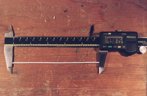
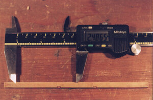
Before the deck clamps can be installed the distance down from the gun port sills has to be established. Taking a deck beam and the waterway measure the total for these two pieces. This measurement happens to be .497.


image102.JPG
Taking pieces of scrap wood, spacers were cut to the measurement of .497. These spacers are used between the top edge of the clamp and the gun port sills. The first plank of the deck clamps are glued to the hull and held in place with spring clamps.


image103.JPG
The deck clamps are made up of three heavy planks. On an actual ship these planks would be made up of planks average 20 to 30 feet long. On the model they are one piece from stem to stern. Second and third plank are held tight to the plank above and clamped to the hull.

image104.JPG
Spring clamps are used all along the hull to hold the deck clamps in place. These planks were bent without having to soak or heat bend them like the wales required.


image105.JPG
Deck clamps are like the wales except they are on the inside of the hull. As the clamps reach the stern they twist and lay flatter than in mid ship. The top of the clamps are cut down level so the deck beams sit flat on them. When placing the deck clamps under the stern gun ports be sure to raise them slightly to give yourself enough room to level off the top.
 
Last edited:
photo1.jpg
The water way is one piece and its glued and clamped to the bulwarks. if you set the sills and the deck clamps up right the waterway will fall right were it should.


photo2.jpg
The waterway fits snug on top of the deck and under the gun port sills.


photo3.jpg
If the gun port sill was not set proper, and either the waterway will not fit under it or the sill is to high and it does not rest on the waterway, don’t worry. Use needle nose pliers and grab the sill then bust it out. It’s not going to come out in one piece but that’s fine.


photo5.jpg
photo4.jpg
What didn’t break out I ground out with the Dremel. Keep a steady hand and don’t hit the top edge of the wales.


photo6.jpg
There will be a little wood left in the corners. At this point use a knife and clean out any wood left.
When the waterway is set in place you can go back and replace any gun port sills. The replacement sill will have to sit on the waterway and set even with the wale. If the sill is a sliver to high just and it down if to low shim it up to match the wale.
 
HATCH COAMINGS


photo 1.jpg
Hatch coamings, companion ways, skylights and other deck openings are all built the same way. The corners of the coamings are fitted together with a lap joint and not with a 45 degree angle like picture frames. The lap joint when fitted has a pin that runs through each coaming and into the beam below it. The lap can be cut at random; the extra length is trimmed after the coaming is assembled.
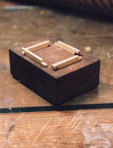

photo 2.jpg
After the pieces are cut assembly is set up so each side has an under lap and an overlap.
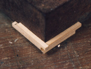

photo 3.jpg
Two sides are glued by placing them against the corner of a square block. Another two sides are set up in the same way.
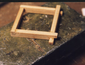
photo 4.jpg

The two assembled corners are now glued together to form the coaming. The extra over lap at the corner is trimmed even.
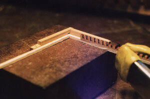

photo 5.jpg
When gratings are used in the coaming a small ledge is added to the inside of the coaming. The added ledge is not all that necessary and the gratings can be glued directly to the inside of the coaming.
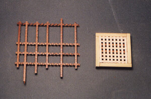

photo 6.jpg
The gratings can be made on a small table saw by following a variety of published methods. When setting up the grating start with an outer square and add strips in both directions. It is easy to get the gratings out of square by starting in one direction. By building the gratings by skipping strips enables you to push on opposite corners to keep it square.

SKYLIGHT
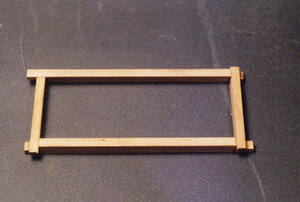

photo 1.jpg
The skylight is set on a coaming. This is built the same way any of the hatch coamings are built. Once the coaming is assembled the corners will be trimmed even.
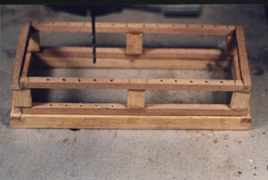

photo 2.jpg
By using the same material used for the ledges a frame work is built on the coaming. A wider material is used for the short up rights. In actual building they would have been attached to the lower and upper frame with a mortise and tenion, on the model they are glued in place. Next an upper frame is set in place. Once the frame is built holes are drilled through the upper frame and into the lower. Protective bars are run into the holes. The bars themselves are made from .025 styrene plastic rod bought at a local hobby shop. The rods are white in color so they were painted black before being installed. No glue was used to set the bars in place.
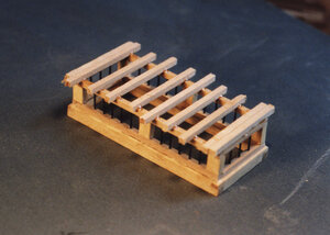

photo 3.jpg
With the bars in place beams are set across the frame work. Doubles are set at each end so the ends of the roof planking will have something to nail to. I didn’t bother to cut the beams to exact lengths. I cut them close and glued them in place.
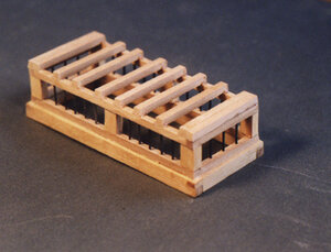

photo 4.jpg
After the epoxy sets up the ends of the beams are sanded flush with the sides of the frame work.
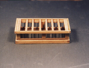

photo 5.jpg
A molding is fixed to the side of the framework to box in the ends of the roof beams. This molding is the width of the roof beam plus half of the top frame. Once in place it will make the structure water tight.
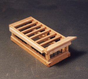

photo 6.jpg
A scrap of wood is added to the side of the framework with two sided tape. This is used as a guild to set the over hang of the edging plank. The edge plank is ¼ wide and 1/16 thick. This is one of the rare areas where a 45 degree joint is used. The end grain of wood tends to absorb water faster than the rest of the plank. Before the joint is set, caulking is used on the face of the 45 degree edge.
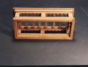

photo 7.jpg
Here the skylight is tipped on its side so you can see the molding and the over hang of the edge plank. At this stage you can add glass to the windows, one suggestion is to use the clear plastic many products are packaged in.
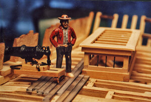

photo 8.jpg
Here the skylight is in place on deck. The decking is an experiment in using a clear plastic planking. There is so much fine joinery in the deck structure I didn’t want to cover it. To put the carronades on the model some sort of decking is needed. Planks were cut from plastic and run through the sander to score the surface so it looked like a grain pattern. The edges were painted black to simulate caulking. The plastic was clear enough you could see the deck structure below it The entire skylight was built off the model. In reality the coaming would be set in place on the beams then iron pins run through the corners and into the beams. The coamings are also pinned to the carlings. Then the rest of the structure is built on the coaming.
 
WALES

The main wales on a ship are a massive belt of planking made up of three to six runs of planking, depending on the size of the ship. On the Oneida the wales are made up of three strakes, or runs of planking making them a total of three feet wide. The front of the wale begins in the rabbit at the stem, runs along the hull even
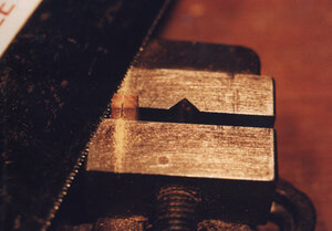
with top of the gun port sills and terminates on the stern blocks. Wales add a great deal of longitudinal strength to a hull as well as protects the ship from cannon fire.


wale1.JPG
Some model builders will cut a planking rabbit into the stem and keel. On the Oneida model there will be no planking below the wales so I didn't cut a rabbit except for the wales. Cutting a rabbit was done by holding the end of the wale against the hull frames and with an Exacto knife; a cut is made along the outside edge of the wale piece.


wale2.JPG
To cut the depth of the rabbit a cutting bur was used. As the bur cuts deeper, keep going back to the outer edge and make a deeper cut with the Exacto knife. As the rabbit gets deeper it gets easier to control the cutting bur to achieve a clean sharp rabbit. Looking at the photo you can clearly see a gouge running off the stem. This is what happens when you let the cutting bur get away from you. To avoid this, after making the outside edge cut, go back and cut off the inside corner so you have a little trench. Then carefully creep up on the finished edge with the bur until its deep enough to prevent the bur from jumping out of the rabbit and across the stem.


wale3.JPG
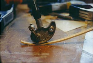
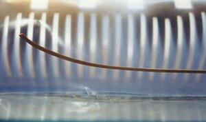
Wales on a ship will take a lot of stress from the required bending and twisting to form to the shape of the hull. To begin the forming process of the wales a glass of water is boiled in a microwave. Then the end of the wale is placed in the boiling water for about 10 minutes. The wet strip of wood is now bent with a hot bending iron. Heat from the iron will turn the water to steam and the wood will have to be soaked again. It will take several soakings and bending with the iron to form the strip to the required shape.


wale4.JPG
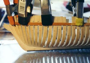
Once the end of the wale has been bent it is soaked one more time and clamped to the hull. Spring clamps are always used rather than the screw "C" type clamp because the "C" clamp leaves a dent in the soft wet wood. So much pressure has to be applied to the wood the dent is very difficult to sand out. As you bend the strip around the bow check the lower edge to make sure it's touching the frames. The strip not only bends around the hull but also takes a twist at this location.


wale5.JPG
Leave the strip clamped to the hull until it has thoroughly dries. Once removed from the hull there will be a little spring back, for the most part the wood will retain the shape


wale6.JPG
The square end of the wale will have to be cut on an angle in order for it to sit in the rabbit.


wale7.JPG
The rabbit is a little too shallow to hold the wale piece in place while its being glued and clamped. The end of the wale tends to pop out of the rabbit so two scrap pieces of wood are clamped to each side of the stem, which holds the wale tight against the hull timbers and in the rabbit.


wale8.JPG
A series of spring clamps are used down the entire length of the hull to hold the wale in place.


wale9.JPG
Wales on the Oneida are made up of three strakes of planks. The edges of the second and third strake are beveled in order for it to sit tight against the lower edge of the plank above it. This bevel will change angle down the length of the strip. Starting at the stem there is only a slight angle then as the wale bends around the hull there will be an abrupt change to the bevel. As the wale approaches and runs along the side of the hull there is only a slight angle. At the stern the wale takes a twist to the lower transom. Here the bevel takes an extreme angle.

NOTE: model builder tend to forget when planks are fit to one another on a curves surface the edges need to be beveled so the planking fits tight to one another in kit building the double planking is so thin beveling the edges is not needed.
 
Last edited:
SWEEP PORTS


oar1.JPG
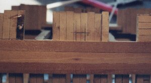
With the wales in place, the sweep ports will we marked and cut in the bulwarks. Exact size of the port is marked using the first bulwark plank. This plank is a little wider than the other planks by standing the plank on end against the top of the wale mark the width.


oar2.JPG
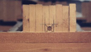
Find center of the square and drill a hole.


oar3.JPG
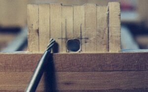
Using a burr grind out the square until you touch the pencil lines.


oar4.JPG
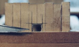
Using a scalpel square out the corners. You are looking very close to the model so the square looks rough. At normal view the edges look clean and sharp.


oar5.JPG
When the planking is glued to bulwark the ends and lower edge of the planks form the sides of the sweep ports. This gives the port a sharp clean look. Looking at the picture this close you can see the wider first plank which defines the size of the port. If you were to use all the same size planks a notch would have to be cut in the next plank up. On the left the plank ends were cut and sanded to the edge of the gun port side. At the top of the bulwarks the top timbers will be trimmed even with the last plank.
 
Back
Top