• LUCZORAMA SHIPWRECK SCAVENGER HUNT GIVEAWAY. 4 Weeks of Fun • 1 Legendary Prize ((OcCre’s Fram Ship)) • Global Crew Welcome!
    **VIEW THREAD HERE**

Rigging question

  • Thread starter Thread starter Thomas
  • Start date Start date
  • Watchers Watchers 7
Joined
May 24, 2018
Messages
416
Points
168

Location
Auckland, New Zealand
Hi, I'm currently finishing up the vintage (1983) Mantua Sergal Sovereign of the Seas (more on the experience later).

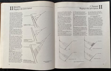
Between the main and mizzen masts there are stays from the mizzen to the mainmast shrouds both port and starboard. I'm not sure if you'd call them crows feet or martnets, but I've shown them circled in red in the photo of the plans.

From an aesthetic point of view, I want to keep the blocks in as straight a line as possible, like on the plans, but I'm finding it really difficult to visualise the best way to do it because there are so many variables. I'm wondering if anyone has any tricks or techniques they might share.

Thanks!
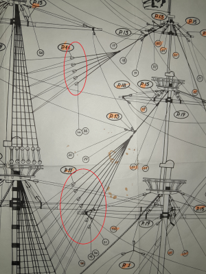
1.png
 
I am intrigued what is the purpose of these blocks and ropes connecting a mizzen mast top with last shroud rope on main mast. Strange that they are connected only to one left side shroud rope. What about a starboard shroud rope? Could someone explain?
 
I am intrigued what is the purpose of these blocks and ropes connecting a mizzen mast top with last shroud rope on main mast. Strange that they are connected only to one left side shroud rope. What about a starboard shroud rope? Could someone explain?
I'm not sure either--martnets usually secure sails. But they are on both sides of the ship, if you notice the lines coming off the bottom block go to two points and those numbers refer to belaying pins on both sides of the ship.
 
I am afraid this all might be just a mistake on the plans by model makers. I can be wrong of course.
 
From an aesthetic point of view, I want to keep the blocks in as straight a line as possible, like on the plans, but I'm finding it really difficult to visualise the best way to do it because there are so many variables. I'm wondering if anyone has any tricks or techniques they might share.
Thomas, I made a jig to create these (I don't have a photo but basically I pinned blocks to a board and then pre-rigged as much as I could before taking it to the model. I also remember using some threads placed temporarily just to get the thing suspended before running the final lines. Wish I could be more helpful.

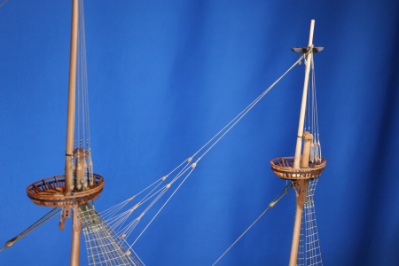
Vasa model:

1741474446294.png

1741474465405.png

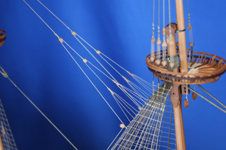
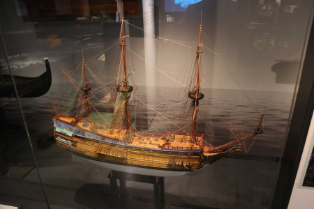
Sophia Amalia (about 1650?):

1741474697813.png


1741474725702.png
 
Last edited:
Sounds like a weak flexible connection. Why not to connect to something solid as a main mast? A mystery.
Because it was unnecessary to attach mizzen forestay to something more solid than a backstay. The mizzen topmast did no require than much support since the mizzen topsail was relatively small. Placing the mizzen topmast forestays outboard instead of central prevents them from interfering with running rigging from the main mast also.
 
Last edited:
The purpose of the multiple blocks was to evenly distribute the tension from the stay across a length of the shroud as well as provide a method of adjusting the tension on the backstay from a position on deck. Getting this bit of rigging looking right is a tricky business. One could indeed make a jig, leaving the backstay "tail" long and then put it all in place by installing the assembly. The real question this experienced full-scale rigger has is "Why aren't blocks also fastened to the shroud because the purpose of running the adjusting line that runs through the "flying" blocks and is belayed on deck was to be able to adjust the backstay tension to suit the sailing conditions?" There would be a lot of friction generated by just running that line around the shroud below the ratline attachment points, probably more than could be overcome) and this would 1) tend to defeat the purpose of the blocks whose pendants were married to the backstay equally distributing the backstay tension across a length of the shroud and 2) to the extent the line from the blocks needed to run around shroud when tightening the backstay, that would cause problematic chafing of the securing line. (Not to mention that chafe on the ratline lashings would create a serious safety hazard!)

If I were rigging for the intended purpose, I would definitely attach blocks to the same points where the drawing has the adjusting line running around the backstay so that the adjusting line would easily run when it was hauled to adjust the backstay tension. From a rigger's perspective, it's not a properly workable arrangement without blocks on the shroud.

If I were doing it on a model, I'd definitely add blocks at the points where the adjustment line is now shown simply turned around the backstay, thereby achieving a working purchase to the backstay tension adjusting tackle. I'd then temporarily seize the "flying blocks" to the backstay proper, leaving excess line at their bitter ends, but not so tightly that the length of each block pendant could not be pulled through the seizing to adjust its length as desired. I'd then attach the backstay proper to the mast. With that done, I'd reeve the backstay tension adjustment line through the blocks as otherwise illustrated in the instructions and when the adjustment line was riven, I'd adjust the final lengths of the "flying block pendants so the blocks were all in line and simultaneously adjust the tension adjusting line so there was no slack between the shroud blocks and the "flying" blocks. Then I'd belay the tension adjusting line to its pin or cavil on the rail and clap on permanent seizings to marry the "flying" block pendants and the actual backstay (which presumably should be larger cordage than the pendants) and trim the excess bitter ends of the pendants taking care not to mistakenly cut through the actual backstay itself. (Don't ask me how I know that! :p)

I'll also mention that #14, the adjustment line hauling part is rigged bass-ackwards, leaving it to lead down from the lower "flying block" This puts the hauling part of the adjustment line running out in the middle of nowhere aloft and prone to fouling something. The proper run of that line would be back to an additional block attached to the shroud and thence down to the deck running parallel to and immediately adjacent to the shroud, keeping it out of the way of everything else. (As is shown in the later posted photo of a different model.)

Finally, one should note that this rather complicated arrangement of "flying blocks" is not accessible for service (routine lubrication, etc.) or repair (unfouling or replacement) from anyone other than a trapeze artist! To access the "flying" blocks, the adjusting line would, at the very least have to be unrove and the backstay and "flying" blocks dropped at the mast. Re-reeving the adjustment line would then require an unreasonably long reeving line to zig-zag between all the blocks the entire distance between the mast and shroud where the blocks could be reached and then taken up again to set up the backstay. The proper rigging would be that there was provision made (perhaps a hook and eye or, given the early period, some other method of temporary attachment) to loosen the backstay tension with the adjustment line and then detach the backstay from the mast so it could be attached to a tag line and lowered to lay against the shroud where the blocks could be accessed and then hauled back to the mast with the tag line and attached, the adjustment tensioning line taken up, and Bob's yer uncle.

I always get a kick about these rigging issues that come up with kit plans and instructions. I once had a long discussion on a similar issue with a well-known and highly authoritative author of a very expensive practicum series. He had a mizzen boom topping lift rigged with a "dead purchase" by which no purchase at all could be achieved due to the erroneous placement of an intended topping lift tackle block on the boom. No matter how hard I tried to explain that there was no purchase to be had the way he had drawn it, he refused (somewhat contentiously, I might add,) arguing that that was the way it was drawn in his highly authoritative research source. Indeed, he was right that was the way his research source had drawn it as well. His research source was incorrect as well. Physics and mechanics are what they are. It's not rocket science, but it's a good example of the fact that there's no substitute for "hands on learning." Kit buyers beware! I'm not saying the kit designer didn't know their stuff. Just as easily, the manufacturer may well have said, "We can save the expense of seven blocks here and nobody's going to be the wiser!" :D
 
Last edited:
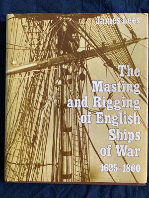
YT…. The book you showed in your first post to this thread looked like very interesting. It appeared to have an illustration backed by some description of the particular rigging. ??? I would be very interested in knowing the title and author and where you found it
 
YT…. The book you showed in your first post to this thread looked like very interesting. It appeared to have an illustration backed by some description of the particular rigging. ??? I would be very interested in knowing the title and author and where you found it
Oh, no problem. Here we go. I got it either at Abebooks site or eBay.

image.jpg
 
Because it was unnecessary to attach mizzen forestay to something more solid than a backstay. The mizzen topmast did no require than much support since the mizzen topsail was relatively small. Placing the mizzen topmast forestays outboard instead of central prevents them from interfering with running rigging from the main mast also.
And nevertheless later on navy people became smarter and started connecting mizzen forestays to the main mast. HMS Victory is an example.
 
Thomas, I made a jig to create these (I don't have a photo but basically I pinned blocks to a board and then pre-rigged as much as I could before taking it to the model. I also remember using some threads placed temporarily just to get the thing suspended before running the final lines. Wish I could be more helpful.

Vasa model:

View attachment 505611

View attachment 505612

Sophia Amalia (about 1650?):

View attachment 505613


View attachment 505614
Hi Paul--Thanks very much, the jig is a great idea and I'll give it a try.
 
Ah, stays rigged with crowsfeet to attach them to other stays and shrouds! The 17th century was a wonderful time. Thanks to Bob Cleek for the detailed analysis of why this is an inherently difficult solution to a relatively simple problem. These crowsfeet were a common solution when standing rigging or the dead ends of running rigging had to be fastened to a stay or shroud. They distribute the load, rather than concentrating it and creating a kink at the anchor point, so that makes some physical sense. I suspect that the crowsfoot attachment was abandoned later in the century when someone wanted to carry staysails on the stays between the masts.

Since all of the topmast and topgallantmast rigging on Vasa was recovered shortly after sinking, we do not have much of the evidence we would want about how this was done on the ship. We are pretty sure that the mizzen stay was run to the port side of the mainmast at about head height above the deck (offset to avoid the main halliard tackle, which was on the centreline), and it is possible that the mizzen topmast stay was led directly to the mainmast just above the top, through a lead block, and down to the deck. There is nothing in the way that would prevent it, and the main topsail halliard, which might foul it, is offset well to starboard. There are two holes in the main top, abaft the mast, which appear to be for leading lines down to the deck that come from above, and the mizzen topmast stay could be one of the these (the holes are about 60 mm in idameter, so large enough). There have been rigging plans published of Vasa that include some of the upper stays rigged with crowsfeet, but that is not on the basis of archaeological evidence, rather using other comparative sources, such as models and paintings of contemporary ships.

We know that crowsfeet were used for some things, since the rigging finds include a number of euphroes, with 4, 5, or 6 holes. There are four 6-hole euphroes found with the mainsail, and these are probably for the main course martnets, but at least one of the smaller euphroes was found on deck in between the main and mizzen masts, so probably came from a crowsfoot rigged between those masts.

Fred
 
Back
Top