• LUCZORAMA SHIPWRECK SCAVENGER HUNT GIVEAWAY. 4 Weeks of Fun • 1 Legendary Prize ((OcCre’s Fram Ship)) • Global Crew Welcome!
    **VIEW THREAD HERE**

Russian Steam Launch

Joined
Sep 17, 2018
Messages
746
Points
353

Location
Berlin/Germany
Dear Friends,

in my work on my Russian Battleship I "bumped into" the 34-foot Steam Launch and figured out a 1/200 and a 1/64 solution.
I do like this tiny model very much - but I do reach the very end of my eyesight.

Here some humble pictures for your kind orientation:
IMG_20241016_120230_198.jpg
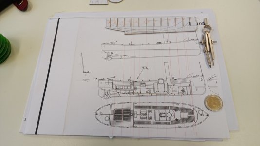
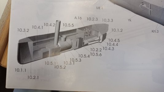
The 1/200 kit's drawing with some twenty pieces...
IMG_20241016_111920_898.jpg
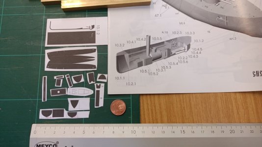
It really is a small model kit in it's own right.
IMG_20241016_115653_921.jpg
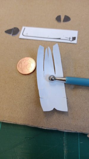
The hull is coming together like a little wonder by the use of my cheap embossing set. I do think about adding a thinest layer of cigarette paper glued inside.
IMG_20241016_120218_170.jpg
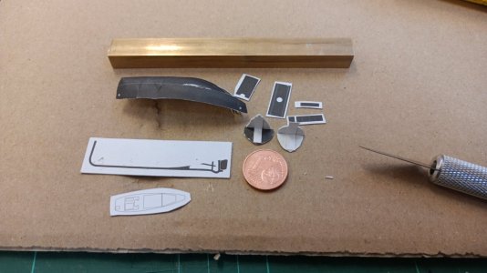
This is the amount of parts I do have to deal with.

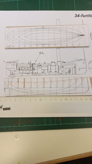
As I was absoloutly exhausted by this little time of working on the model kit, I decided to enlarge the plan from a Polish card model illustrate set onto 1/64 for trial purposes on the topic:
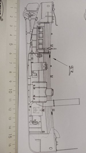
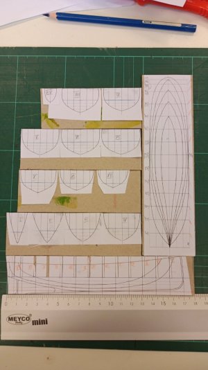
IMG-20241017-WA0004.jpeg

Here the cut CL-board's drawing...
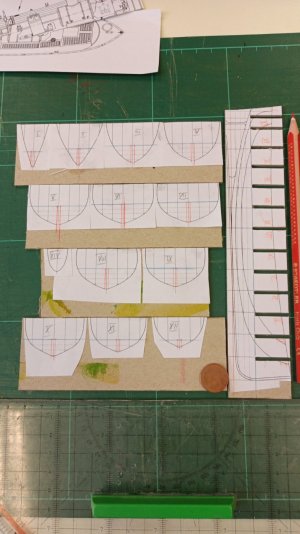
IMG-20241017-WA0000.jpeg
...my first fight with these slots for formers/moulds/bulkheads...
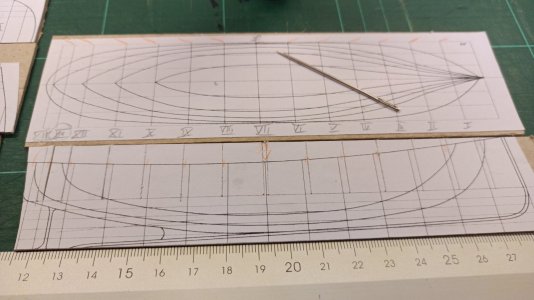
IMG_20241017_131753_778.jpg
...scratching these lines into the 2mm-cardboard with a pointy needle...
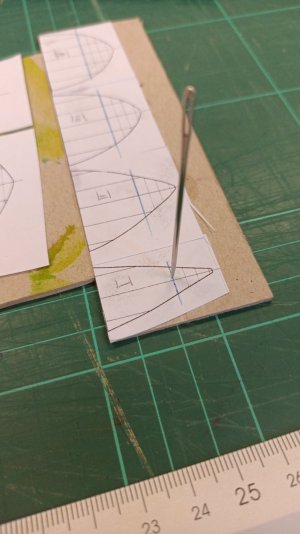
IMG_20241017_133838_730.jpg
So I was luckly able pointing the holes for the slot's grooves positions right into the cardboard and the glued drawing ontop.
Screenshot_2024-10-17-22-32-11-900-edit_org.telegram.messenger.jpg
And enclosed my work with "one single glas of whiskey weekly" as my doctor told me.
 
Last edited:
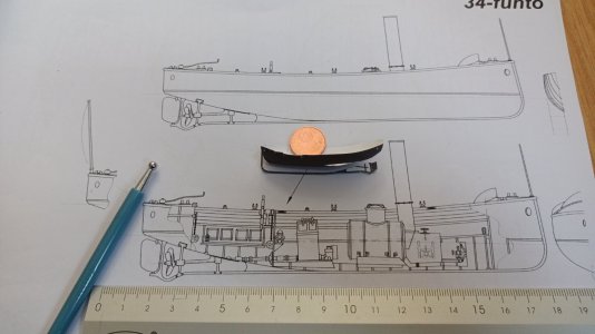
Hello friends, at the very first the comparison between the 1/200 and 1/64 model's size I have been asked for:
IMG_20241018_101313_811.jpg

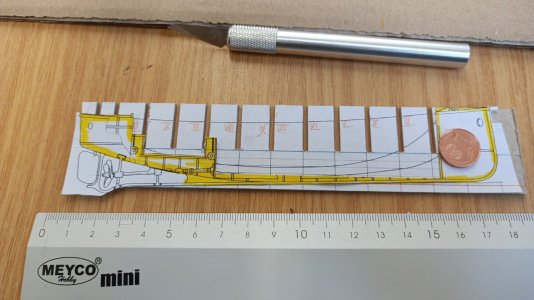
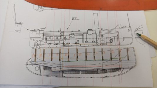
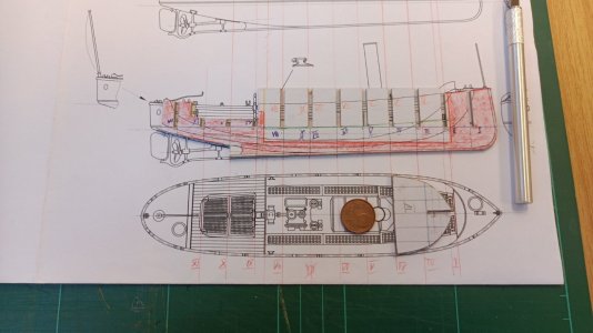
Here today's hole progress in cutting the bulkheads slots into the CL-board and dealing with the real shape of the boat - shown here in yellow. Mould N° II is displaced right infront of the f'c'stl real bulkhead - what can I say?
I do think you do see the trouble I did run into!


Speechless
IMG_20241018_104625_472.jpg

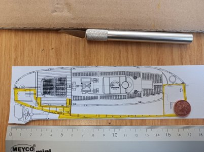
Compared to the top-view it looks like a reasonable solution for the model:
IMG_20241018_104454_002.jpg

So I may be able to get some structural thinks done by using the bulkheads as formers:
IMG-20241017-WA0002.jpeg
We will see tomorrow what is possible to do - hopefully.
 
Last edited:

Yesterday there was a bit of good progress:

IMG-20241021-WA0001.jpeg
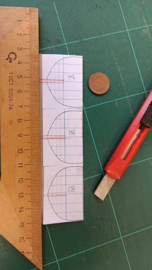
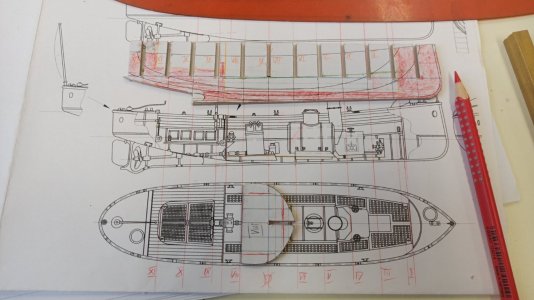
By cutting the bulkheads' slots in the CL-board; and marking the 2mm contra-slots into the bulkheads (red lines) I was able to get some nice results:
IMG_20241021_142016_848.jpg
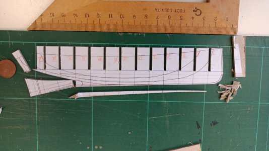
After this I certainly had to overdo it and so tryed to cut away the "dead wood" of the boat and by this too much I did lost the aftermost pice of the stern:
IMG_20241021_143412_828.jpg
These were the most recent tasks, pitties and results.

I am still dealing with the construction of the thin hull parts and the building of the centerpart of the boat. Without building an empty hull in moulds first - filling the floor and the stern and stem structures into it...

But how to do this!? :oops:

So again a little bit of work signed a step of real progress.
 
Last edited:
A short view into the Crystal Ball:

My next step will be an even more complex boat I did buy:

1000029859.jpg

A twin-masted boat of the Monitor RUSALKA class in 1:35 (reduced downwards to 1/64) scale. By this I will come later on towards the nice nickel plated small
361085_800.png
Polish_20241009_105314159.jpg
image006.jpg

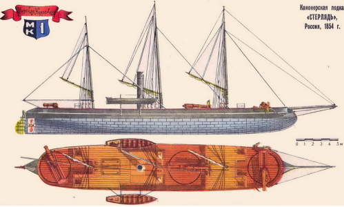
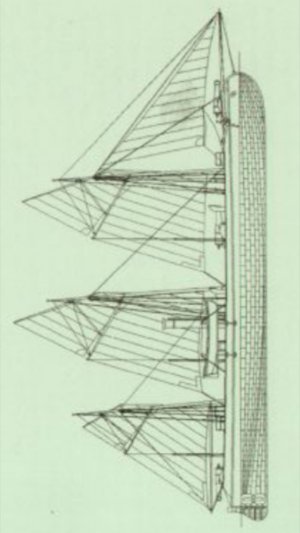
Russian gunboat STERLYAD of 1855 and
1000029858.jpg

the ill-fated Russian Coast defence monitor RUSALKA...

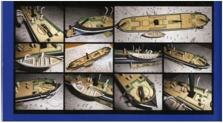
As both builds are from medium detailled plan sets of the Russian Admirality - so it is necessary these builds were supported by a 1/100 cardboard kits STERLIAD out of W.M.C. publishing detailling
1000029856.jpg

all the places where no information is available in the drawings about the Details of staircases or the bulkheads:
1000029849.jpg

and

Screenshot_2024-08-25-12-57-38-820-edit_com.android.chrome.jpg
the RUSALKA by Orel Publishers (in a later lightly altered version) of the Baltic Sea monitor. After this there will be the skills and knowledge for further Russian (Coast) Battleships of the ADMIRAL USHAKOW class:
russia-general-admiral-graf-apraksin-1899-battleship.png

Certainly I do have to try my skills in something less luxuirous decorated as a first step - due to this the
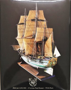
Model_of_Aurore-BSG_218-IMG_6739.JPG
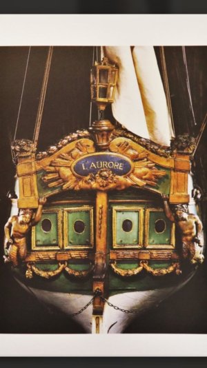
Pleasure Ship L'AURORE by G.Delacroix/Ancre Monography-Nice
IMG_42581 (1).jpg

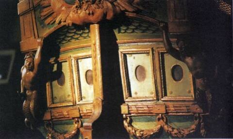
...to get closer to carvings and the much more complex wooden architecture
Polish_20240121_193756188.jpg
of the transom and the figurale detailling in a lesser number on the storyboard of the stern's detailling.
poupe_10.jpg


Why this pile of smaller and easier models? By this workaround I do plan reentering my splended

IMG_20241010_211735_119.jpg
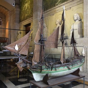
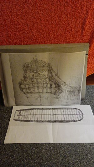
recently moored AKERBOOM 1664 project (here the much more detailled GUDEON transom by v.d.Velde) to be fit for the challanges and problems of the build of a baroque ship - hopefully...

07-10-28_piranhas.jpg
 
Last edited:
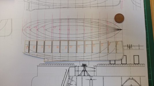
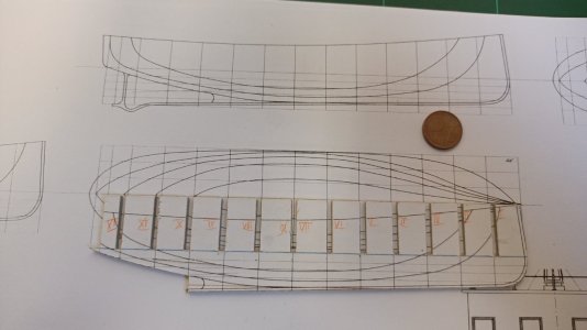
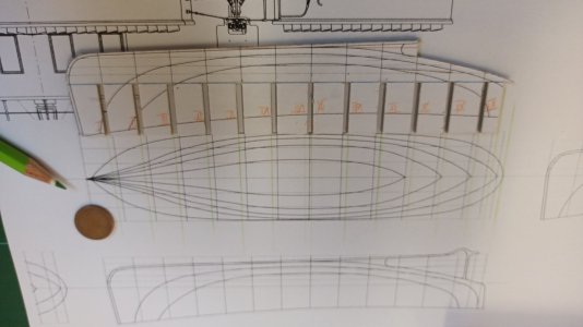
Today's first steps to the hull's finished under water curviature we're done:
1000029897.jpg

The first attempt wasn't precisely enough drawn:
1000029899.jpg

But a good foundation to show the finished parts to fill the under water lines with cardboard:
1000029902.jpg

So the 2nd trial was better (beside the main former not being placed exactly enough) in result:
1000029899.jpg

The next trial was done by using the 2mm-cardboard instread of a measurement by a ruler:
1000029900.jpg

and certraily a pointy pencils:
1000029901.jpg
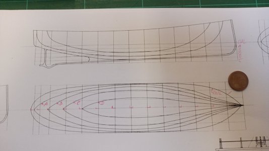
So this is the result even in the photocopy:
1000029904.jpg

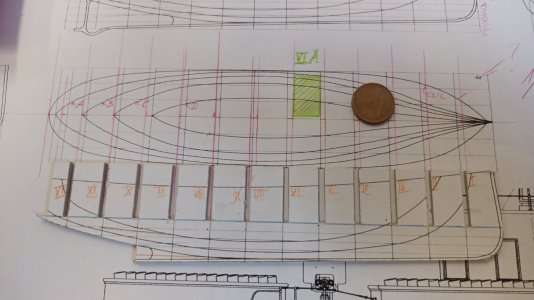
Here is what I try to get out of this shown as a "Green Area" - the horizontal (WLine A) underwater hull slides between CL-board and WLs (being a segment of bulkh'd VI) to add a bit of stability into the construction:
1000029903.jpg
Doing this I will have to lift the engine's and boiler's floor a bit - simplifying the hull's construction by feaking deep into the hull by weathering. Never tried something like this... :cool:


But the results of today's Work are bringing back to me the old rule of geometry:

"Construction will always
beat any measurement!"


(Some pictures will come here later on.)​

1000029897.jpg

1000029898.jpg
 
Last edited:
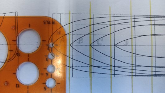
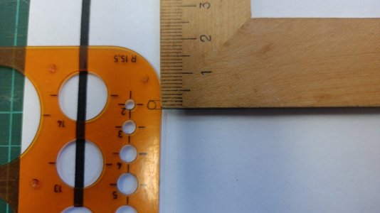
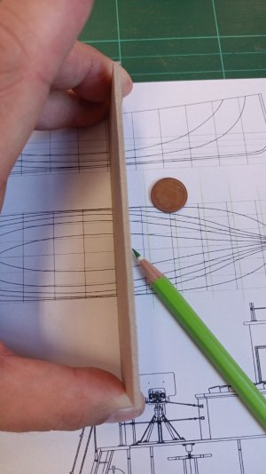
My first attemnpt to draw exactly 2mm - the thickness of the cardboard - not too great results at first:
1000029907.jpg

I tried and got here the result:
1000029905.jpg

A two millimeters circle as I wanted to get it.
 
Today is HappyMouldsDay!

1000030044.jpg
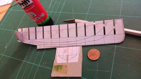
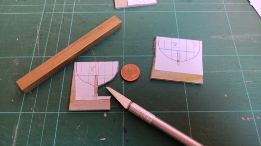
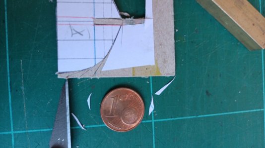
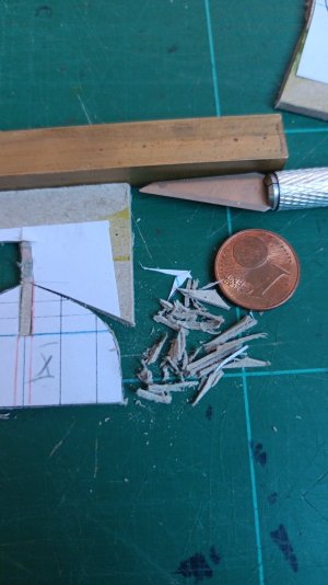
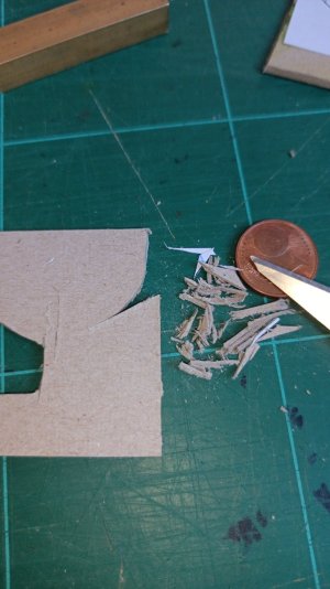
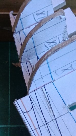
Here how to cut out the moulds without sanding:
1000030045.jpg

First cutting the easiest tangente (without any risk to touch the inner body:
1000030046.jpg
Then I started cutting out pointed wedges (a lot of) to a pile:
1000030047.jpg

P.T.O. :-)
1000030048.jpg

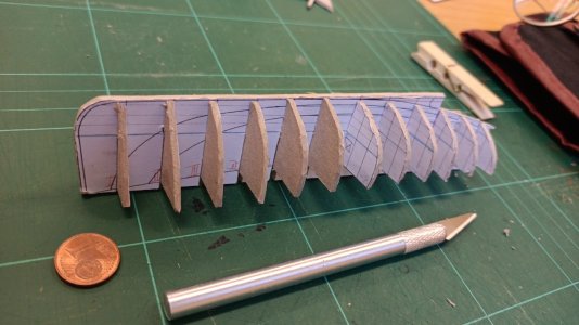
The CWLs of the CLboard and the moulds do come closer to eachother:
1000030049.jpg
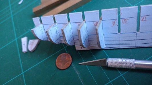
Here the all the aft moulds (mainly) in position:
1000030051.jpg

To bevel the moulds I will just soak them with cyan glue to get a material I can Work with - without spreading layers and layers and layers...

Next is to decided what to do to form the inner space. I do want to use as much of the moulds as possible.


I do think about a tricky beast of full ends and think mid outsides. @Ab Hoving used stripes of softer cardboard for the outside of His models - but I am affraid this will too thick. And in reality these are formers with panking I will have to place the soft cardboards stripes between the formers. :eek:

What do you think?
 
Last edited:
Here today's progress not a lot but highly important:
1000030248.jpg
I figured out where to place the different lines for the engine's and boiler's floor and the well's floor by pointing the ends:1000030249.jpg

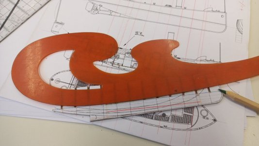
Then using the ''curve ruler'' to find the line of the bent floor of the seats' Line:1000030250.jpg

Here we are with floor's line in red as the minimum of "keel" that is left:
1000030251.jpg

And the red surface is now the space that is to be left:
1000030252.jpg

I hopefully can avoid the slim part below the slot of bulkhead II - a dangerous leck of material to work with!

1000030253.jpg
But how to fix problems of stability in the "rump of bulkheads" that is left - after the cutting away of what has to dissapeare?
 
Thanks @rtibbsbut it isn't that small...
1000030253.jpg
I did chose the 1/64 scale for easier eyeview.

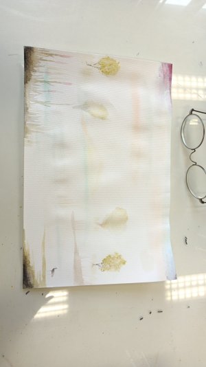
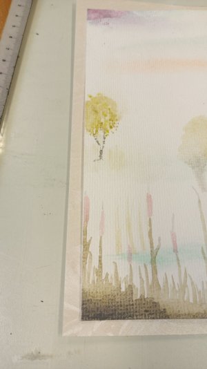
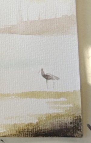
By the way I did some ideas into a small watercolour paint

1000030338.jpg
By this I did learn my lesson,
1000030339.jpg
it is a lot easyer to work on as I call it "morning fog" - so he is eating all problems away... ;)

1000030377.jpg
So keep away from trouble;
do not mess with unthinkable details. Das away from the Impossible but so much beloved and admired...

Put into your work
you do
only what fits in
do not try to push more into it than really
belongs into it...


Needed half a century to come to this conclusion.
 
Last edited:
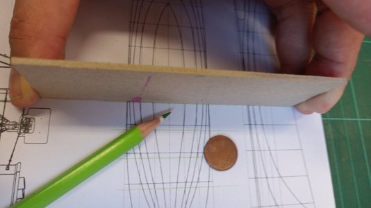
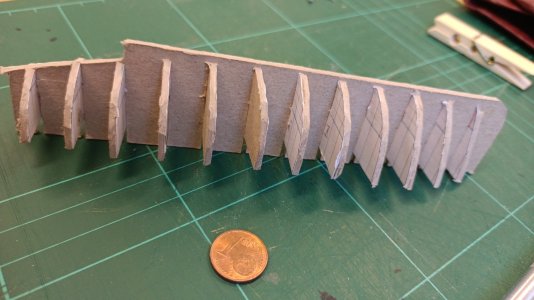
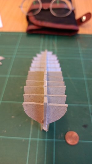
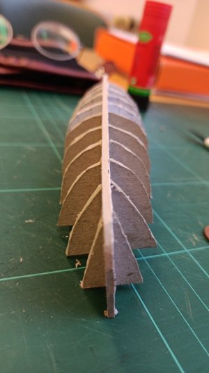
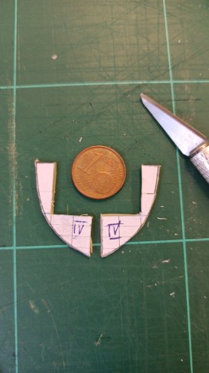
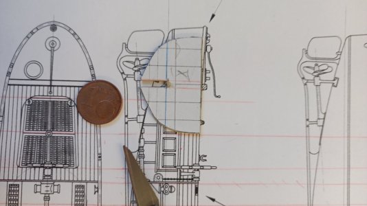
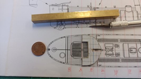
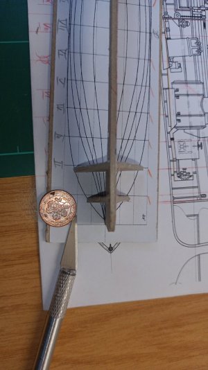
This is today's work's output:

IMG_20241105_141420_598.jpg

Cutting the CenterLine-Board for the helmman's well and the engine and boiler. Some parts will be sliced into two:
IMG_20241105_142337_165.jpg

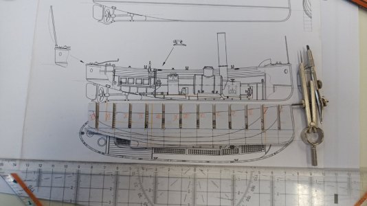
Every bulkbead has to be constructed seperadly out of top- and siedeview:
IMG_20241105_143018_239.jpg

so the measurement are found in both layers:
IMG_20241105_143552_430.jpg

IMG_20241105_144216_942.jpg

The bulkheads do start to fit to the WLplan but I am not very happy about the slim bulkwalk I do have to build admidships - or more precise without the very first stem and sternbulkheads.

So let's see what is going to be tomorrow...
 
Last edited:
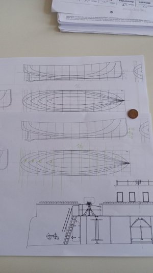
Back
Top