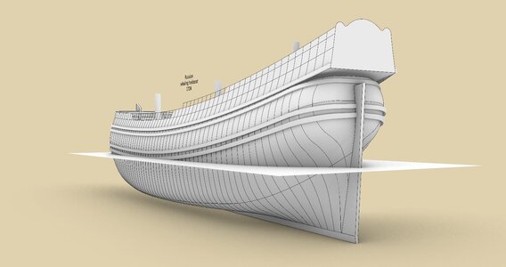
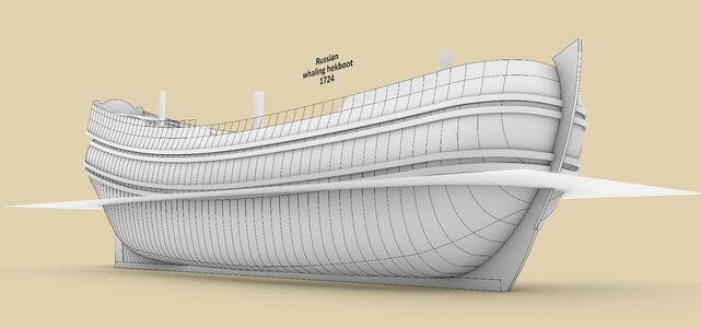
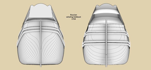
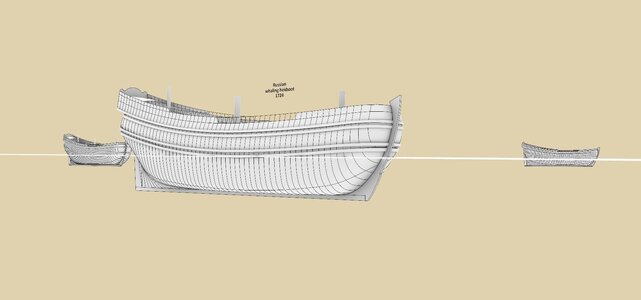
Russian whaling hekboot 1724 – introducing diagonals into Dutch design

Joined
Apr 26, 2023
Messages
540
Points
353

Location
European Union
.​

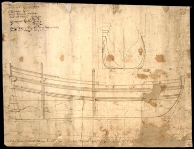
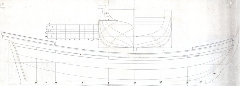
As the title of this thread suggests, this important plan from the early decades of the 18th century demonstrates the next stage in the development of design methods in the Northern Continental/Dutch tradition. This particular plan of a Russian whaling ship of 1724, kindly pointed out to me by Martes, was drawn by an experienced commercial shipwright from Arkhangelsk, Nikifor Bazhenin, for the construction of three whaling vessels intended for the newly formed fishing company – Whale 1725, Greenland Ship 1725 and Great Fishery 1725 (for more on this see V. V. Bryzgalov, O. V. Ovsyannikov, The Project of Peter the Great: State-Owned Fishing Company ‘Kola Whaling’ (1723–1760), [in:] Collection of Works of the Arkhangelsk Centre of The Russian Geographical Society, 9/2021; in Russian).

An interesting special feature of the concept of this vessel is that it illustrates the process of introduction to traditional, existing design methods in the North Continental/Dutch tradition of a relatively new invention – the increasingly prevalent design diagonals. It should be emphasised that the diagonal, still singular in this design, is not merely a verification, but a legitimate design element, actually used to form the shape of the ship's hull.

On the other hand, this design is still firmly grounded in the North Continental/Dutch tradition, as the base of the design is still the ‘flat’ surface forming the bottom of the hull. Nevertheless, the rather ingenious – indeed quite straightforward – use of the design diagonal has made it possible to easily obtain bilge sweeps of variable radii and consequently to form the hull shape in a more flexible way. It could also be said that the concept of this design is quite similar to the design of a Dutch frigate ca. 1700 described in the thread Dutch heavy frigate ca. 1700 – engineering or carpentry ‘snowman’ making?, whilst at the same time being already noticeably more advanced.

Reproduction of the original plan of a whaling ship from 1724 (Russian archives):


Whaling sship 1724 - reproduction fom paper.jpg


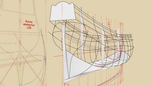
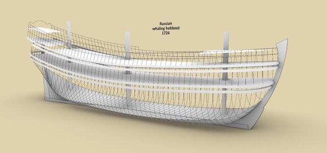
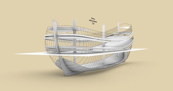
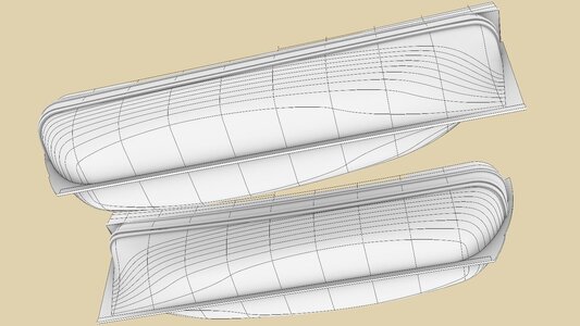
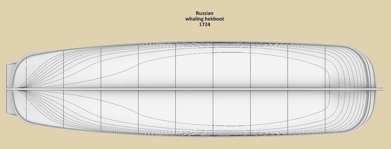
And some already-made graphics illustrating the ship's hull shapes, obtained with a new, fairly recent design system (compared to previous, 17th-century practices):


ViewCapture20240723_133058.jpg


ViewCapture20240726_201927.jpg


ViewCapture20240726_202314.jpg


ViewCapture20240726_202720.jpg


ViewCapture20240726_203122.jpg


ViewCapture20240726_205404.jpg


ViewCapture20240726_204342.jpg

.​
 
.​

The result of the use of this new invention, the design diagonal, cannot be overestimated. Despite the rather difficult, very bulky hull form, the resulting shapes of the hekboot are very good in terms of smoothness, while at the same time there is no longer any need for additional reconciling sweeps for this very purpose (as to the smoothing properties of reconciling sweeps see entries #36 and # 37 in the thread Pinas 1671 by Nicolaes Witsen – the backbone of the fleets | Ships of Scale).

It may no longer be common knowledge today, even among those with a general interest in the subject, that smooth/regular hull shapes are important not so much from an aesthetic point of view, but are above all an extremely important hydrodynamic factor, strongly influencing the quality of movement of a submerged object in a liquid. The graphics below show the resulting waterlines.


ViewCapture20240728_195316.jpg
ViewCapture20240728_195043.jpg
.​
 
Last edited:
It seems to me that we see here a deliberate attempt to maximize the volume of the hold without increasing the length of the ship and maintain rudder effectiveness, and actually now that we see the waterlines plan, I like the run of the hull aft, towards the rudder very much.
 
.​

Hi Maarten. Indeed lovely and the same time somewhat unexpected shapes, if one looks solely at the original plan. It now turns out, for me personally thanks to Martes, that the Russian archives are a veritable mine of ship plans from this early period, including those designed by Dutch immigrants or their disciples using precisely Dutch methods, which were used very extensively in Russia to build transport ships, at least in the first half of the 18th century. This can now be seen as a kind of missing link, and the very existence of this arch-interesting and much-explanatory material can probably be attributed to the centralised Russian bureaucracy forcing designers/shipwrights to provide plans in graphic form on paper (as opposed to Dutch customs and practices). As an added bonus, these plans are usually drawn quite neatly and precisely, which to some extent makes them easier to examine today.

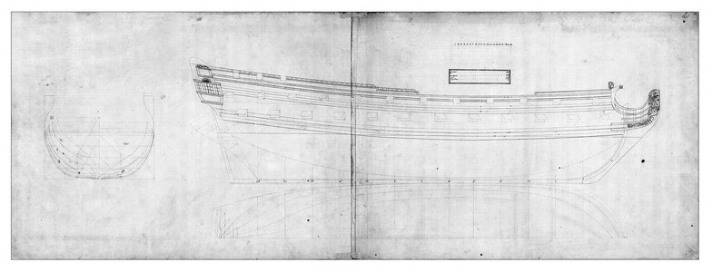
Below is one such example of a Dutch design from the first decades of the 18th century. A wonderfully precise drawing. Those interested will immediately see the line of the ‘flat’ and the ‘boeisel’ line on it:


skerbot ca. 1725.jpg

.​
 
.​

Hi Maarten. Indeed lovely and the same time somewhat unexpected shapes, if one looks solely at the original plan. It now turns out, for me personally thanks to Martes, that the Russian archives are a veritable mine of ship plans from this early period, including those designed by Dutch immigrants or their disciples using precisely Dutch methods, which were used very extensively in Russia to build transport ships, at least in the first half of the 18th century. This can now be seen as a kind of missing link, and the very existence of this arch-interesting and much-explanatory material can probably be attributed to the centralised Russian bureaucracy forcing designers/shipwrights to provide plans in graphic form on paper (as opposed to Dutch customs and practices). As an added bonus, these plans are usually drawn quite neatly and precisely, which to some extent makes them easier to examine today.

Below is one such example of a Dutch design from the first decades of the 18th century. A wonderfully precise drawing. Those interested will immediately see the line of the ‘flat’ and the ‘boeisel’ line on it:


.​
Indeed very interesting and maybe not so suprizing that the Russians made all these efforts to document these design as they didn't had this shipbuilding history yet themselves and imported the knoweledge from Netherlands and England, as can be seen by the visit of Peter the Great to Amsterdam and London.

Do you also see early English designs?
 
.​
Do you also see early English designs?

Unfortunately, I cannot see the entire contents of the archives, but on the basis of the bit I can see, I venture to conclude that the English design methods were primarily reserved for large, seagoing warships. This is evident not only from the plans that I know of, but also from one very telling statement made by a Russian admiral in the context of the construction of these very whaling ships of 1725, that it was not appropriate to send a naval shipyard employee to assist in their construction to Arkhangelsk. Instead, Dutchmen may be sent working under contract in Russia at the time, on the grounds that, after all, these were cargo ships.

An example of such a very early plan of warship (in the context of Russia) in the English convention, and which do not come from Peter I's collection, is the project of a 54-gun ship, which incidentally was used a few years ago to build a fantastic replica of the ship-of-the-line Poltava 1712 (easily googled). I have also shown fragments of this very plan in the thread Hampton Court 1678 – perfectly generic design, in entry #6:


54-pushechnyy_korabl_nachalo_18_v(1).jpg


And the Poltava's replica itself:


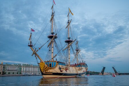
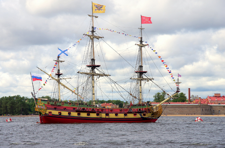
poltava-ship-in-front-of-winter-palace.jpg


And still one more photo of the same replica ship after its 'camouflage' has been updated lately (photo provided by Martes):


Poltava 1712.png


What I really like about this very replica is that it has been built in a fairly close to the period-appropriate manner and largely with authentic materials. Unlike, for example, today's pleasure yachts made of composite materials and the like.

.​
 
Last edited:
.​

According to the dimensional specifications in extant written documents, the three whaling hekboots to be built in 1725 were to have the following dimensions:

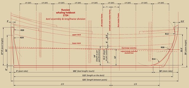
Length (on the deck): 115 feet
Breadth: 30 feet
Depth (from keel to lower deck): 14 feet
Height between decks: 6 feet
Height of bulwark from higher deck: 2 1/2 feet

They agree perfectly with the dimensions measured on the examined plan. Besides, after taking additional measurements of the plan, it can also be said that this is another example of a ship designed according to the ‘golden’, i.e. perfectly typical proportions of the main dimensions proposed in contemporary Dutch works on shipbuilding (length : breadth : depth = 4 : 1 : 0.4).


Main dimensions, keel assembly and lengthwise division

– the total length of the ship (between posts) was determined by multiplying the ships's breadth by four (or vice versa),
– the keel has been drawn as a straight line, and the rabbets of both posts have the same height (measured from the underside of the keel),
– the sum of the rakes of the two posts was set at 1/6 of the length of the ship, and their ratio to each other at 9:1. In this way a sufficiently large rake of the stem post was obtained, required for a ship sporting very bluff lines of the hull’s entry (in horizontal plane),
– the depth in hold value was set at a customary 1/10th of the hull length.

Note: there is a severe anomaly in the design regarding the position and trim of the waterline. In fact, it is almost certain that it was originally set half a foot lower at the master frame and its original trim was three feet. Only later, for some reason, it was moved up by half a foot and given the lesser trim of only one foot.

– to determine the position of the leading (conceptual) frames, the hull was divided into nine equal parts (with a spacing of 12 feet), still according to the original run of the waterline. At the bow, the first station has been set at the intersection of the original waterline and the rabbet of the stem,
– the design features double master frame, fore and aft, which is also a relatively new invention, respectively at the 4th and 5th stations (despite somewhat misleading denomination, these both master frames are not quite identical). The third, ‘virtual’ main master frame falls in between them, roughly at 1/3 of the keel length (note: the contour of this 'virtual' main master frame is not defined at all for the actual construction of the ship, nevertheless its lengthwise position has been used in this design to establish the run of some of the main longitudinal design lines).


ViewCapture20240730_135215.jpg

.​
 
there is a severe anomaly in the design regarding the position and trim of the waterline. In fact, it is almost certain that it was originally set half a foot lower at the master frame and its original trim was three feet. Only later, for some reason, it was moved up by half a foot and given the lesser trim of only one foot.

I operate with data from later times, but Gardiner mentions not once that many ships designed for inclined waterline sailed, in practice, better when evenly trimmed. It is possible that experience with similar ships required adjusting the waterline to increase maneuverability during tacking and overall weatherliness.
 
.​
I operate with data from later times, but Gardiner mentions not once that many ships designed for inclined waterline sailed, in practice, better when evenly trimmed. It is possible that experience with similar ships required adjusting the waterline to increase maneuverability during tacking and overall weatherliness.

Yes, this could well be the reason for the correction of the waterline inclination. Besides, it occurred to me later, that the original height of the waterline (at the master frame) is precisely 1/10 of the length on deck, while the final height is 1/10 of the total hull length (i.e. between posts).

Be that as it may, virtually the entire design was made to follow the original design waterline, with the result that later the level of the greatest breadth fell exactly half a foot below final design waterline, that is the difference of the height of both waterlines. This can be considered a kind of aberration, however, in this very case, without much detriment to the lateral stability of the ship, I guess, as in cargo vessel the gravity centre safely remained very low anyway.

.​
 
.​

Longitudinal design lines

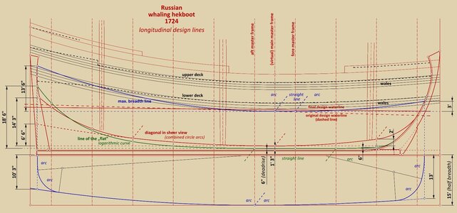
In order to subsequently form the contours of all leading frames (for the underwater part of the hull), four longitudinal design lines were used:

– upper edge of the keel,
– the conventional line of the ‘flat’ (forming the bottom of the hull),
– diagonal in side projection (new invention),
– line of the greatest breadth (originally at the level of the waterline before it was altered; not parallel to the wales).

Not all of these lines were drawn or left on the original plan and the run of these missing lines had to be reconstructed.

In particular, it should be emphasised that all three curves, which make up the contours of all the individual frames, have been formed on the body plan using the diagonal, consequently the prior defining the run of the main design lines (apart from the line of greatest breadth) on the top projection is no longer necessary; it is sufficient to define them only on the side projection. To put it another way, the design diagonal in this project has very conveniently replaced the narrowing line(s) that hitherto had to be defined on the plan view.

Attention can still be drawn to the very low position of both main design lines (‘flat’ and diagonal) for nearly all the length of the hull on the side projection, which translates into a very full shapes of the hull sporting a large payload. Except, naturally, for a rather short section in the aft part for at least sufficient effectiveness of the rudder. In addition, the sharper run noticeably improves the ship's movement even at low speeds as well.

It is also shown on the diagram that the very blunt, ellipse-like shapes of the breadth line, at both ends of the hull, have been formed by means of combined circular arcs.

One last thing – where the line of the ‘flat’ (green) is below the diagonal line (red), the shape of the frame will come out convex, and where it is above it will come out concave.


ViewCapture20240801_000238.jpg

.​
 
Last edited:
.​

Body plan

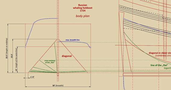
Typical of the North Continental/Dutch tradition, the whole game starts with the formation of the bottom surface of the hull – the ‘flat’. The cross sections of the ‘flat’ (green) were created by connecting the corresponding points on the keel and on the diagonal, the latter partly replaced the hitherto used exclusively for this purpose the line of the 'flat' (for the procedure see the diagram below). The connecting curves are purely straight lines in this design, although for the last frame it should rather be an arc of a large radius, which was probably left by the draughtsman to the more convenient, easy correction by dubbing already during the construction itself.


ViewCapture20240801_180922.jpg


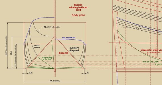
In the next step, futtock sweeps were defined, which lower points coordinates were taken from the intersection of the horizontal lines starting from the already defined run of the diagonal on the side projection and the second, auxiliary diagonal on the body plan (see diagram below).


ViewCapture20240801_182137.jpg


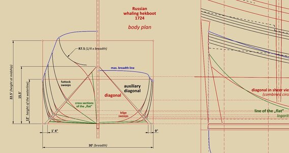
In the last step, the two sets of curves were connected by tangential arcs passing through the intersection points of the same previous auxiliary horizontal lines with the proper diagonal (see diagram below).


ViewCapture20240801_190655.jpg


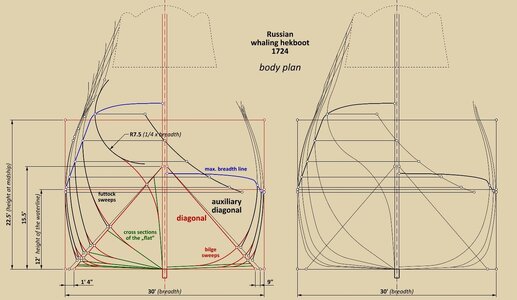
In this ingenious, technically elegant way, it was relatively easy to obtain variable radii for the sweeps that make up the contours of the frames, resulting in impeccably smooth shapes for a hull sporting, after all, a rather difficult, bulky form. The complete body plan, already including the upperworks, is presented in the graphic below.


ViewCapture20240801_193905.jpg


* * *​

This early design method in the North Continental/Dutch tradition has also hardly been recognised and described in the modern literature. As a result, modellers and recreators of ships of this period are unnecessarily restricted to rather wild guesswork and shaping the hull by eye, which, however, in more challenging cases can scarcely be considered a satisfactory methodology.


Thank you for your attention,
Waldemar Gurgul

.​
 
.​

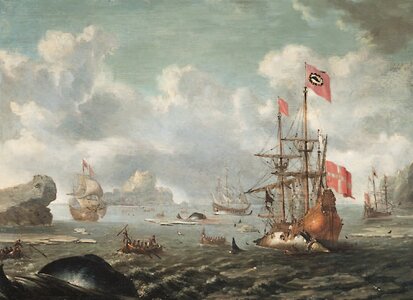
I have recently found a particularly fitting image here of a whaling ship, created in the very last decades of the 17 century, sporting this peculiar concave shape of the stern at the level of waterline, quite rarely rendered by artists, as being well visible in practice only when the ship is still unloaded or has been bow angled for some reason. As a result, I simply could not resist posting this reproduction, as if to compare and confirm this peculiar shape, but also to enrich the thread with a certain artistic cut.

The reproduction is taken from the publication by Klaus Barthelmess and Hendrik Busmann, Zwei Walfanggemälde des 17. Jahrhunderts aus der Sammlung Hugo Bruhn im Deutschen Schiffahrtsmuseum, [in:] Deutsches Schiffahrtsarchiv 25, 2002, pp. 19–40.


Stuhr (Johann Georg) - Danish Whaler in the Arctic Ocean.jpg

.​
 
Back
Top