Ship line development

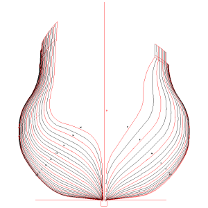
If you have a CAD program, load the drawing into the screen and trace the station lines and then add the missing frames. It will not be exact if you divide the spaces evenly, but, it should be close enough to fair them by sanding. The below has the station lines that were missing on the body plan added.
Allan

1731428523284.png
 
If I understand your plan, as your drawing does not show all frames you intend to add those not shown on your draught by calculating the shape based on the rules outlined in Dean’s book. If my understanding is correct, what you plan to do has a very high probability of nor succeeding.

A draught (or drawing) prepared in a design office was not used directly by shipwrights to shape the ship’s framing. Instead, it was used by the loftsmen in the mold loft to make full sized patterns. To do this they drew a full sized set of hull lines on the mold loft floor. This required “fairing of the lines” as very small inaccuracies on the drawing would be blown up many times resulting in areas that required correction. There are also cases where the ship’s designer intentionally made changes to the design during the lofting process. The original draught was not necessarily corrected to reflect changes made during the lofting process.

Once everyone agreed that the lines scribed on the mold loft floor were correct full sized patterns of structural members could be made. This included frames not shown on the draught. These “missing frames” were not derived mathematically but were instead plotted from graphic information on the mould loft floor.

The correct way for you to determine the shape of these missing frames is to “loft” your draught. To do this you should first redraw the draught that you have to correct any distortion. Once you have an accurate set of lines; waterlines, body plan and buttocks, drawn to the full scale of your model you can add those missing frames using graphic information from your drawing. You can either do this the way that I would by hand on a sheet of frosted Mylar or if you have access to CAD you could scan your draught into your CAD program and go from there.

I also believe that Allan’s suggestion of making approximate oversized missing frames and fairing them on the model should work too

Roger
 
Hi Roger
This is an interesting exercise. Different folks are seeing things I may have overlooked, forcing me to layout my plans. I have the sheer and half breadth for whatever they are worth. If I measure all of my offsets, including those for the additional "missing" frames, I can plot them to my hearts content on a body view or as individual frames. The big question is how to connect the dots. I have done this for airplanes (Waco YMF) by using French curves. I did not have to do this on 100 or so frames.
Looking at the body view for Bellona one can see the various points used to generate the curves. I have been assuming this was done via compass set to the correct radius and the correct origin. If this is correct, I should be able to connect the dots in the same manner. If I can I think it would be more repeatable, frame to frame, than fitting with a French curve.
If I am completely wrong, I can always resort to light table, sharp pencil and many sheets of paper.
If I resort to tracing I have a problem near the max breadth region as there is no spacing between the curves. I would have to make all of those frames fat and then sand to fit. I really do not want to do it that way. It also has an impact on attempting to fair the inside of the frames. They would also have to be oversized and sanded to fit.
I have AutoCad Lt and used it on the airplane. Tracing curves is a real pain. I have looked at FreeCAD but my first attempts at fitting a curve have been disappointing.

Am I completely out of my mind?

warren
 
I should add that I am a retired electrical engineer. I went to a technical college in central California. We were taught all kinds of fun stuff, a lot of it having nothing to do with electronics. Having a bit of free time now I can go back and do things that had been set aside. I am always eager to learn how things were done. Having that extra fun stuff in my education lets me understand fluid flow, mechanics optics and such. I have spent a bit of time racing Fireballs as foredeck ballast. And a fair amount of time at the bow in 38 to 50 foot boats of different type, bay racing and off shore.. My one of my room mates was a naval engineer. Now I am looking at some of the stuff he (Carl S.) used to talk about. He and I sailed a few times on his "Star." Fun little boat. We both thought it would be fun to sail on a square rigger...for about one day.
Anyway, I'm trying not to be stubborn, I really want to know how some of the drawings were done. For what it is worth, if you go through Dean's hull development, his arithmetic is wrong. He is not off by much but it made me go back and look at me CRC tables.

warren
 
A Naval Architecture Lines Drawing is nothing more than an orthographic aka three view drawing that you will be familiar with if your engineering education included mechanical drawing. The body plan is the end view, the half breadth the top view, and she sheer plan, the side view. The key concept is that each and every point on one view must occupy the same space on the other two. Eg; a point on the side view will be the same height as that shown on the end view, likewise that same point on the end view will be at the same distance from the centerline as that shown on the top view.

Ship lines drawings are more complex as they define curved surfaces. Now, if you just trace the body plan sections, you have no guarantee that the points defining these body plan sections will match those on the half breadth plan. AND that they will line up in such a manner that waterlines on the half breadth plan will be smooth curves. This is why lofting is required!

Roger
 
Another thing about lines drawings is that no two draftsmen are likely to produce exactly the same drawing. In other words there can be several slightly different drawings all of which can be considered to be the correct solution. This is because of fairing, the process of passing a smooth curve through a series of plotted points. Each draftsman will use his own judgement in doing this.

Young engineers today seem to expect exact results from their work but in this case even different CAD programs may produce different results because CAD relies on algorithms to make these judgments and different CAD programs may use different algorithms. A Naval Architect was known to comment that no matter what data he entered into his CAD program the resulting design looked like a J-26. ( a popular modern sailboat)

Roger
 
Original source of "Drafting Ship Plans In CAD" is the Nautical Research Guild.

Here is their site with more articles:

NRG

Andreas
 
Back
Top