• Ships of Scale has incorportated an extra level of security when you log In. Please follow on-screen prompts to acknowledge that you are not a robot via a "Check Box" or a "Pictorial Check Box Puzzle". This is needed due to higher level of AI Activity Security.
  • SUBSCRIBE TO SHIPS IN SCALE TODAY!

    The beloved Ships in Scale Magazine is back and charting a new course for 2026!
    Discover new skills, new techniques, and new inspirations in every issue.

    NOTE THAT OUR NEXT ISSUE WILL BE July/August 2026
  • Win a Free Custom Engraved Brass Coin!!!
    As a way to introduce our brass coins to the community, we will raffle off a free coin during the month of August. Follow link ABOVE for instructions for entering.

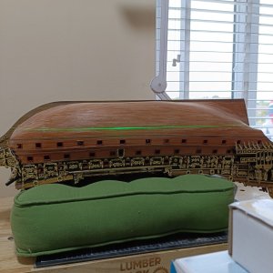
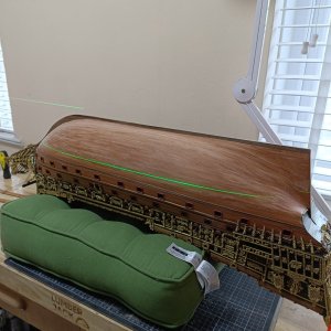
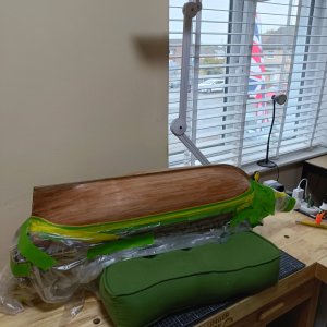
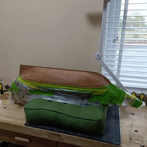
Sovereign of the Seas - Mantua by Brian

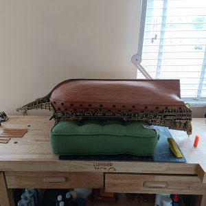
What do you think? right colour?
I like it!!!

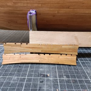
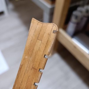
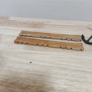
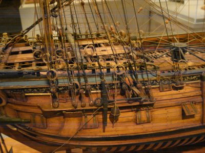
For the future, the channels had holes for the deadeye iron work to pass through in the 17th and most of the 18th century. This changed to slots and the simple moulding type batten over the outer edge of the channels for the British Navy to facilitate the removal of the deadeyes in 1771. There was no moulding on the fore and aft edges. There is a lot of great detail on the channels and knees in The Construction and Fitting of the English Man of War pages 184-188.
Allan
 
Last edited:
You had to show a laser didn't you??? :):):) Your post (which is a great one) cost me money as I think it is a great way to mark the waterline so want to invest in one. Just need another application to sell the idea to the Admiral......
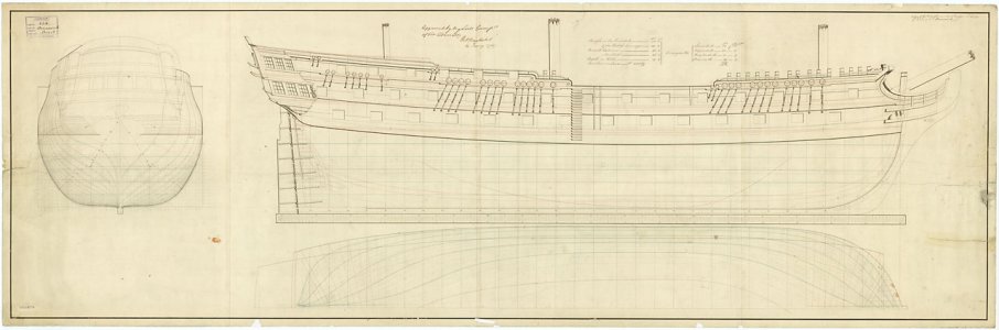
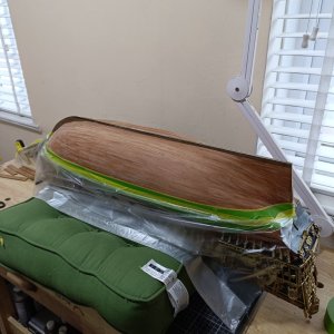
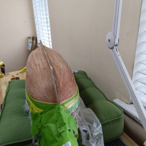
As to where it goes, this is also a great point. Which waterline do we use? I did some digging and found the load draft dimensions for English first rates through small boats in both the Shipbuilder's Repository 1788 and Steel's The Elements and Practice of Naval Architecture which are both in Scantlings of Royal Navy Ships.

These may not apply to your ship but if you wish I can post the dimensions from the above books.

Allan
1788292849938.jpeg
 
Last edited:
Thank Bri, I may just do that, but she is WAY smarter than me and recognizes a line of BS quicker than I can hand it out.

Just as an FYI, if SoS is similar to first rates built in the early 18th century, the 1719 Establishment gives the figures for the load line. For a first rate of 100 guns and a burthen of about 1800 tons (a bit more than SoS) the load draft was 21 feet 6 inches above the lower line of the rabbet at the bow and 22' 10" abaft. By the later 18th century, the Shipbuilder's Repository 1788 give the line forward at 23' forward and 24 feet aft. The line was measured from the lower line of the rabbet, not the bottom of the keel. As the paying of the bottom was slightly above the load line there is some flexibility. I do wonder if the height forward and aft being different would even be noticeable.

Have fun with the laser you lucky guy!

Allan
 
Just to chime in on the waterline:
The ship's designer, Phineas Pett, tells us that the swimming line was 18 feet 9 inches from the keel's bottom at the midship bend. These early 17th century ships drew about 2 more feet of water at the stern than at the bow, so you would be pretty close if you had it draw 19 feet 9 inches at the stern, and somewhere around 17 feet 9 inches at the bow. If all goes well, the gun ports at the midship bend should be 5 feet from the water (this information is again provided by Phineas Pett). Measurements of the Sovereign tell us that the stern chase ports were 6 feet from the water, and its reasonable to assume that the bow chase ports were also this distance from the water.
 
Back
Top