Spritsail Rigging

Joined
Jul 10, 2021
Messages
1,466
Points
393

Location
Vancouver Island
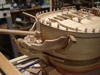
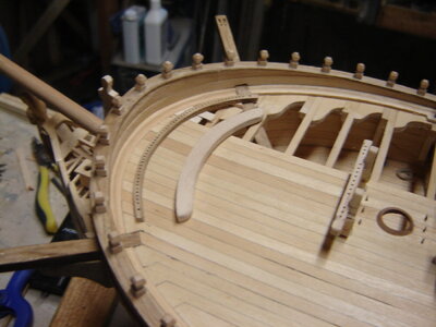
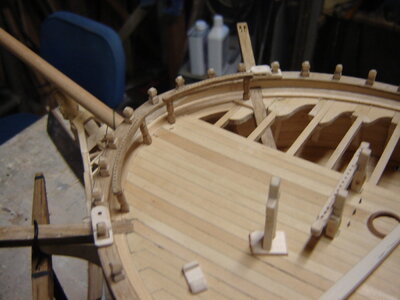
In Petersson's " Rigging Period Ships" on page 112 (Kindle in my case) (page 99 in hard back book Thanks Jack)he shows the spritsail rigging terminating on/by the bulwarks somehow. Are these terminations on ring bolts on the deck or bulwark? I just spent two days making a beautiful curved pin rail and then noticed that all the stuff on the bow doesn't seem to be on a rail. :)
 
Last edited:
In Petersson's " Rigging Period Ships" on page 112 (Kindle in my case) he shows the spritsail rigging terminating on/by the bulwarks somehow. Are these terminations on ring bolts on the deck or bulwark? I just spent two days making a beautiful curved pin rail and then noticed that all the stuff on the bow doesn't seem to be on a rail. :)
Hi Don,
From what I understand Petersson's " Rigging Period Ships" book is based on the 36gun frigate Melampus and looking at belaying plan 'B'(page 99 in hard back book) all the rigging from jib, flying jib and spritsail are belayed to either timber heads at the bow or to belaying pins on pin racks attached to the bulwark on either side of the bow. Can't see a reason not to use your pin rail on Discovery.
Cheers JJ..
 
Thanks Jack. For an example of what I'm looking for can you look at the Spritsail lift. It looks to me like it's terminated on the inside of the bulwark on possibly a cleat? Petersson drew pinrails as they really looked so I'm curious as to what kind of a termination these are. They don't look like a timberhead as a timberhead would be in the middle of the cap rail. I do have lots of timberheads to use. Would they terminate more than one thing per timberhead?
So as it is I could use a pinrail, cleats on the bulwarks or the timberheads. Decisions, decisions :)
Thanks for your help.

DSC04741.JPGDSC04742.JPG
 
This may or may not apply, because the rigging on this ship is from 1636, but here is how the French and Dutch rigged the spritsail lifts then.

A sling was used to lash the yard to the bowsprit, and the ends of the yard had pendants. The halyard for yard can be seen attached to the center of the spritsail yard.
912-prepare-sling-for-sprit-yard-jpg.151677


The lift lines start at the forestay line, are roved through the pendants and then run back up to blocks on the forestay located a bit farther down the stay line. The lifts are rove through these blocks and down to the gammoning, where they are belayed around the gammoning. This arrangement is highly variable between ships and between time periods. That is why many rigging books do not specify the belaying point, leaving us modelers confused with no guidance on how to belay the lines. This problem is common to most lines in running rigging. Ships of a similar size/nationality/period can be safely cross referenced with regard to belaying points, and using such information has a high chance of being correct. However, without similar vessel examples, the solution becomes much harder to make, and without any reference info, you are left with only guesswork. You should try to look for examples of how these lines are run on a similar vessel during research, or as a final resort, use the same belaying point that other modelers have chosen for your ship.
1122-rig-sprit-yard-brace-lines-jpg.178867
 
Thanks Kurt. I've learned that lesson and I try to stay within about 20 years or so of the Discovery. Fortunately Petersson's example, the Melampus,1785 fits fairly well. I also follow the Swan series but I've followed it so much that I'm now trying to find other ways to do things so that it doesn't look like I built a Swan and stuck the Discovery name on it. Vada's Vulture has cleats on the breast hook(?) so I'm trying to stay away from that. I just thought that someone would have an idea of what Petersson was belaying the Spritsail ropes to on his Melampus. Would there be a strength issue with the belaying points. I did read somewhere that the lightly loaded ropes were belayed on the pin rails but I'm not sure if the spritsail ropes were considered lightly loaded.
 
I just noticed that Charlie added a couple of pin rails to his Fly to deal with this. Post 23
 
In my experience, given no direct indication of a specific belay point, if a pin rail is available in the correct location I default to the pin rail belay point…
 
1. Lines from the spritsail mast and sail(s) could be belayed almost anywhere that was logical and sensible.
That would include bollards, ring bolts in the foc'sle deck, pins in a rail attached to, or a part of, the main rail, shroud cleats, ring bolts in the spritsail yard, etc, etc,etc. During the 17th and most of the 28th century there was no fleetwide standard.
2. The one way that I have never seen is to attach a pin rail flush onto a deck, such as the foc'sle as you have shown, and to push the pins through the rail and the deck ending with the tip of the pin in the hold. The reason is the following - in order to secure a line to a pin, you have to have access to the bottom of the pin. The line wraps around the top of the pin, is pulled down to the bottom of the pin, wrapped around the bottom of the pin, is then pulled up to the top of the pin where the process of wrapping up and down is repeated several times. This whole process is finalized in one of several ways again involving access to the top and bottom of the pin. You can not get to the tip (or bottom )of the pin if it is the hold - that is a bigtime problem!
3. You probably need to remove the pinrail that is mounted flush with the foc'sle deck; my guess is no ship ever built had this detail.. You can replace this flush mounted pnrail with a series of eyebolts with (or without) rings. You can think of eyebolts as a sort of universal standard detail since almost every ship (warship and/or commercial ship) built had eyebolts with or without rings installed somewhere (or everywhere); even to this day. If your plans show such a detail, they are simply in error.
 
I had to improvise on where to belay spritsail sheets and spritsail tacklines.

Cleats were placed on the beakhead deck for belaying the spritsail sheetlines.
1134-bowsprit-sail-rigging-complete-jpg.179319


I scratch built some pin rails in the inside corners of the beakhead to make a place for the sprit topsail sheet lines. No way of knowing if this was the correct arrangement for a this type of ship, so I made a guess. At least the lines are easily accessible.
1140-rig-sprit-topsail-sheets-via-blocks-on-sprit-yard-to-belaying-pins1-jpg.179324
 
1. Lines from the spritsail mast and sail(s) could be belayed almost anywhere that was logical and sensible.
That would include bollards, ring bolts in the foc'sle deck, pins in a rail attached to, or a part of, the main rail, shroud cleats, ring bolts in the spritsail yard, etc, etc,etc. During the 17th and most of the 28th century there was no fleetwide standard.
2. The one way that I have never seen is to attach a pin rail flush onto a deck, such as the foc'sle as you have shown, and to push the pins through the rail and the deck ending with the tip of the pin in the hold. The reason is the following - in order to secure a line to a pin, you have to have access to the bottom of the pin. The line wraps around the top of the pin, is pulled down to the bottom of the pin, wrapped around the bottom of the pin, is then pulled up to the top of the pin where the process of wrapping up and down is repeated several times. This whole process is finalized in one of several ways again involving access to the top and bottom of the pin. You can not get to the tip (or bottom )of the pin if it is the hold - that is a bigtime problem!
3. You probably need to remove the pinrail that is mounted flush with the foc'sle deck; my guess is no ship ever built had this detail.. You can replace this flush mounted pnrail with a series of eyebolts with (or without) rings. You can think of eyebolts as a sort of universal standard detail since almost every ship (warship and/or commercial ship) built had eyebolts with or without rings installed somewhere (or everywhere); even to this day. If your plans show such a detail, they are simply in error.
That pin rail was just laying there when I took the picture, I wasn't planning on attaching it there. Sorry for the confusion. This is what I've decided on, although it's not glued yet either :) I left a gap in the middle so they could get to the head.

DSC04747.JPG
 
Back
Top