Stern Decorations - Hahn Drawings - Prototypes

combining etching and cutting, can 3D produce in wood (instead of 3D printing) figureheads or even figures themselves because of limit of 90 angle and woulds scale+burn make this impossible? Can a larger piece be rotated?
Great observations and questions. Let's discuss this a little bit.

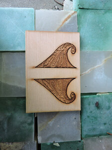
With a few special exceptions, nearly all of our laser Vector Cutting is done in 2D. By this I mean, we are viewing it above as if a sheet of paper, just like a normal drawing, and we send the output to the laser similar to the way we would a standard printer. All of the cuts through the wood are at a perfect 90 degree angle. There really is no true 3D sculpting or shaping done by the laser. With a laser, to create 3D decorations, we cut out multiple parts with the laser, assemble them together and then do the final shaping by hand. I call this Laser 3D Assembly. We already see this in modern kits from CAF, MarisStella, and the upcoming Trident Alert. In many cases, they even provide jigs to assist in the delicate assembly of the very fine laser cut parts. Laser burn (char) is not a problem with a specialized modeling laser such as the Epilog as that can be adjusted and controlled during prototyping. When I mentioned combining etching and cutting I was referring to the actual etching of decorative artwork directly on the part prior to cutting it out with the laser. We can also etch artwork onto wood before or after it has been CNC carved as well - more on that later. Another thing we can do is 2-sided etching, where we etch artwork on both sides of a piece with symmetry, such as interior walls and doors, etc. Epilog lasers are also capable of remaining in focus while etching across a slightly curved surface - within limits. I do this every day etching glass drinking tumblers and what not. In addition, I also have a rotary attachment for my small laser that allows etching around a column shaped object even if not symmetrical - within limits. The rotary attachment turns the object, similar to a lathe but much slower, while the laser sweeps across etching.

However, in the long run - using a laser for 3D carving of figureheads, wreaths, and other types of sculptures is NOT the best way to go. For this we would use a CNC machine. My Shopbot CNC machine runs on 3 axis... X, Y, and Z... the Z-axis (vertical) has 6 inches of travel. This allows me to use 3D bits to carve along the vertical side of an object as well as left and right. We call this 2D+ carving. Because my CAD software has very advanced 3D functions I am able to perform 2-sided machining on my CNC. So I can take a thick billet of wood, carve in 2D+ on one side.... flip the wood over... carve a perfectly matched 2D+ on the other side to reveal a perfect 3D object. We could take this even further and use the 3D Assembly concept and carve multiple 2-sided, 3D objects and then assemble them together into something larger. The fit will be perfect because it was created and manufactured under computer control. Once the design is perfected.... it is DONE... replicate thousands. There is a possibility that we may get a 6-DOF (6 degrees of freedom) CNC machine in the future... but that is up to the Admiral... A 6-DOF CNC would allow full 3D machining without flipping the wood.

All of this stuff will be demonstrated and more as we progress along.... But I want to make sure we go slow enough so that EVERYONE can follow without too much trouble....

Questions are always welcome... the more everyone understands, the better models we can build!!!!
 
Last edited:
Mike,
Can you also do 3D scanning or you specialise "only" in using drawings for input? A few years ago I made some inquiries regarding 3D scanning (figure heads), using the resulting cloud for 3D printing or CNC carving. This cloud had to be excessively edited (they estimated about 40-50 hours work per piece only for the edition) so I had to let the whole thing go because of its astronomical costs. I assume technology has changed since then... Yes and the other problem was reproducing the crevices in the carvings because the 3 axis carver just could not make them.
János
 
Can you also do 3D scanning or you specialise "only" in using drawings for input?
Great questions Janos. I do not have the 3D digital scanning equipment you mention. Currently, the price point on those devices is out of reach and primarily used in automotive and aerospace industries. The resulting 3D computer file, whether scanned or drawn is the same, although high-end scanners typically result in higher resolution and have many more data points causing very large file sizes. For these digital scanned objects to be rendered to print on "consumer" level 3D printers requires a ton of editing to actually "downsize" the resolution of the file.

The 3D object file we are talking about here is commonly called an STL file (stereolithography). These are native files used by 3D printers. Remember back to our very first post.. 3D printing is a form of ADDITIVE FABRICATION... where CNC and laser is SUBTRACTIVE FABRICATION. Two different things all together. For a lot of fabricators it is very difficult to take an STL file and convert it into something a CNC machine can carve (to your point).

Guess what friends.... Here at SoS, we have some pretty advanced capabilities. I can take any native STL file made for 3D printing and render it for CNC carving. The more detailed the STL file the BETTER!!! I have the proper tooling to get down into those tiny crevices and carve boxwood perhaps to a finer level of detail than even the best 3D printers!! Most of my 3D carving bits cost over $100 each and go down as small as 1/64". I even have carving bits as small as 0.1mm that I have yet to experiment with!!

Back to the beginning - it all depends on the original artwork. I have some very high-end fabrication equipment and software but I am not a 3D artist. That is where the collaboration is needed!!

Hope this helps to answer your question. Please bring more!!
 
Hey Mike...
So....lets see if I understand this. When producing a true 3D object (with your current technology..), you don't have the capability to machine around corners or around circumferences. To do so would require either the workpiece or the cutter to move "out of plane" like a CNC lathe would do. So you cut 3D objects about half way then finish the cut from the opposite side.......
It would seem like maintaining registration of the workpiece when you invert it would cause all kinds of trouble.?? Of course, you obviously manage it..:)
It's just hard for me to imagine inverting a workpiece and putting it back down in precisely the same X,Y orientation to the cutter.
Sure glad I don't have to do it.!!
 
It's just hard for me to imagine inverting a workpiece and putting it back down in precisely the same X,Y orientation to the cutter.
Yes, Howard, you got it exactly correct and that is exactly how I do it. The precision comes with the toolset!! My CNC machine is made by Shopbot. Shopbot is located in Raleigh, NC and produces some of the best CNC equipment in the world. When I flip the work piece over... the registration remains perfectly precise!! This will be demonstrated in a future post once we get deep into the CNC side of things.

For now.... go take a look at the Shopbot website.. Especially since they are in your very own state!!

 
for Mike and me it is a designer meets fabricator i can draw but my drawings need to be translated to the fabman he is the "how to make it guy"

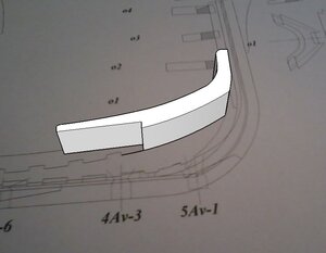
i drew a flat drawing of the design how to bend it to fit the hull ?


confed02.jpg


it's the bottom piece of the quarter galley

confed01.jpgconfed04.jpgconfed05.jpg

here is the shape
my first thought,
the actual surface is a slight curve if i made it flat i could etch the design work on the face of a block and carve out the back side until it fits against the hull

confed03.jpg
 
i drew a flat drawing of the design how to bend it to fit the hull ?
First of all, that is a wonderful drawing design Dave!!! So, how to "make it".

Your way will indeed work and would be the conventional approach. You could also build up the shape with modeling clay and then carve the remaining detail into it to match up with the laser etch wood placard. Doing this of course requires a one-at-a-time approach, some carving skills, and cannot be repeated consistently many times. In-fact, it might even be difficult to perfectly duplicate your decoration for the other side of the quarter galley.

A high-tech approach, would be to take your design file, import it into Vectric Aspire 10.5 and extrude it vertically into a 3D shape by adding a defined amount of z-axis. Much of this is automatically accomplished by this very intelligent software. We can then further refine the shape manually from there. Once complete, we save the file as an STL or CRV and pump it over to my CNC post-processor for toolpathing. Then we let the Shopbot CNC carve it. This may take us a few attempts through prototyping.. but once it is done... it is DONE... bang out a 100 of them. Then we simply do a mirror-reverse for the other side of the ship. From there every copy of this decoration will be exactly the same and fit perfect every time, assuming the modeler has built the underlying structure properly to plans.

Am I making sense here? Do we want to see more???
 
Mike,
Talking about z axis extrusion... how does the software create an arc (or rather, in 3D, a cone) surface to extrude to? If it can, it would really result in that gallery shape what Dave was asking about.
János
 
how does the software create an arc (or rather, in 3D, a cone) surface to extrude to? If it can, it would really result in that gallery shape what Dave was asking about.
Well yes. This is where the hours and skill with the software comes into play. In general, the more expensive the software, the more advanced features it will contain. But the flip side of that coin is, the more features the software contains, the longer it takes to learn. If it is a good software package, there will be constant upgrades and added functionality. Just in the past year my Vectric Aspire has been upgraded from 9.5 to 10.0 to 10.5. Each time brings HUGE new features. The good thing about Vectric is they provide full video based tutorials on each and every aspect of their software. With this software it is possible to manipulate 2D and 3D objects in any shape, fashion or form your imagination can dream up. The only thing to hold us back is the learning curve and the number of hours to work on a particular project. This is why when you see a large movie production such as Pirates of the Caribbean that has a ton of CGI effects, they may have over a hundred or more people working with 3D software to get the work done. Vectric Aspire is one of those such packages and it is 100% suited for model design and building.

What is the catch? Price. This software is made for professionals and costs $2000 for a one year subscription. This is why you don't see software like this being used in our relatively small model building world... not even by the so called "big players".

So, Janos, I am going to answer your question by not really answering it... yet!! We will for sure be getting deep into the topic of 3D and CNC carving but we have only just begun exploring 2D and laser etching. So, we have to go at a pace for everyone to ride along.

But I am not going to just keep you hanging out there...

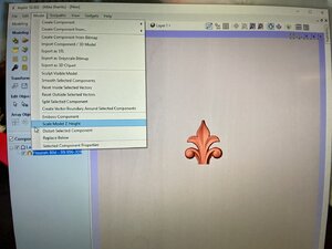
Take a look at this screenshot. Here you can see a menu of just a very few of the functions we can perform on a 3D model. Most of these functions also have sub-functions under them. For example... we could increase the z-height of the flourish model shown but then slice off a small portion of the top leaving it flat. Or we could increase the z-height in a triangular or dome fashion which would automatically distort the flourish shape to fit. We could thicken the base of the flourish to add material for the modeler to manual sand away himself. We could use a software chisel to manually sculpt the model ourselves. We could add additional components to the flourish to create a larger model (3D assembly). We could do all kinds of distortions to the shape of the flourish. After we have completed whatever we wanted to do.... we could send the design out to our CNC machine.... OR we could export it as an STL file so anyone could print it on a 3D printer.

Is this beginning to make more sense??? I hope this helps without actually demonstrating the work you asked for....

IMG_0285.jpg
 
Mike,
I am a Solidworks professional so I know quite a lot about 3D design and stuff. SW is a package for engineers (and very expensive, after the $10,000 purchase price I had to pay an annual fee of $2,000 for 'maintenance'), so not really done for free shapes like what we use in model decorations. But everything can be done with it. I designed Duyfken's hull in it and it went OK. So I am watching your journey through a SW glass!
Keep up the good work!
János
 
I am a Solidworks professional
Fantastic!!! I hope I did not offend you as I was explaining to the larger group as well. I don't know much about Solidworks other than the general description but fully appreciate it's capabilities. So, my assumption is you already knew the answer before you asked.. LOL. Ok, cool. It is difficult to tell through forum post questions who is novice and who is expert, so I always try to explain things very basically. Vectric Aspire is a combination of CAD, 2D and 3D modeling in a single package.... It also comes with a HUGE library of pre-rendered 3D shapes that can be used for model building. In addition, it has the post-processor for my CNC machine and allows me to simulate my CNC jobs before actually running them.... Great stuff.

You should send me one of your small/simple STL files and let me see if I can fabricate a prototype!!! Would love to try. I am already doing similar work with others behind the scenes. I am what they call here in the states a "maker".
 
Last edited:
Mike,
Talking about z axis extrusion... how does the software create an arc (or rather, in 3D, a cone) surface to extrude to? If it can, it would really result in that gallery shape what Dave was asking about.
János


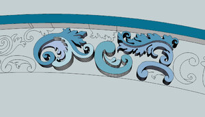
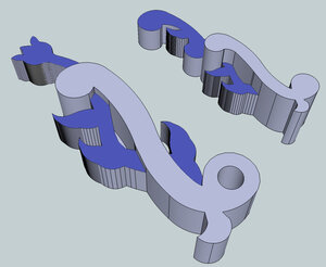
to extrude say a piece of the stem the shape is drawn and you just give the Z a dimension like this example. This is a basic and can be done in 99% of all 3D software.

3dd.JPG


more complex shapes are first drawn in 2D the extruded

as7.jpg


this is the basic block piece, block refers to a sculptures term (blocking out) a forum or roughing it out to get the shape. Detail is added by rounding out the edges and adding detail.
Once this is created and saved as a STL file a maker should be able to CNC this piece

as2.jpg
 
a piece starts as a 2D cad file like this

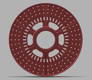
center hub1.JPG


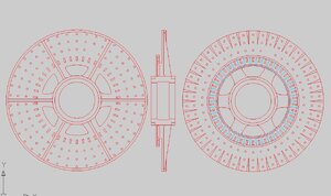
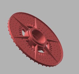
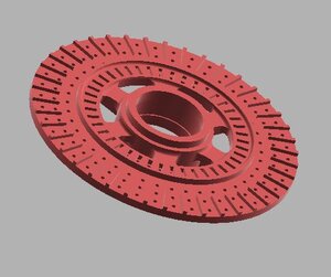
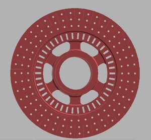
that file is then 3D modeled and the results are this, these are STL files and those would go to the makers either a 3D printer, CNC machinist or a mold maker to make a production mold for casting.

This kind of 3d modeling is done by the pros and not something done by a hobbyist just dabbling in 3D work


hub 3d1.JPGhub3d2.JPGhub3d3.JPGhub3d4.JPGhub3d5.JPG
 
Last edited:
This kind of 3d modeling is done by the pros and not something done by a hobbyist just dabbling in 3D work
Dave explains this side of it better than I do.... once again, he is a commercial graphic artist.... I am a maker/fabricator... this helps everyone begin to see the difference. We both need expensive software and expensive hardware to create the parts model builders ultimately use!!
 
one reason we do not see much of this kind of work in our hobby is because in the hobby/craft industry model ship building is so very small and the customer base can not support the high cost of the software, the tooling be it a CNC mill or a high end 3d printers, or laser cutters other than the small hobby lasers, nor can the hobby base afford the cost of the professionals to do this kind of work.
 
CAD drafting or in the days when i was learning drafting it was called mechanical drawing. A teacher once told me it is the same as any drawing you are passing along information in your drawing. You have to be able to get that information across to the maker in old day a pattern maker who made a wooden part for making a mold or a machinist who can look at your drawing and know exactly what it is.
CAD drafting is not something you just do, yes you can learn the basic software but "mechanical drawing" is another level of learning.
 
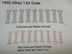
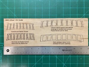
Let us continue and talk a bit about 3D Assembly. Today we will focus on Hahn's HMS Alfred in 1:64 scale. Thank you Dave Steven's for the outstanding scale CAD drawings. We want to just use the laser with a combination of etching and cutting to create parts we can assemble together to begin forming up the stern windows of the Alfred. This is only for demonstration purposes and as we will see later on, there is a much better way to make the 3D Corinthian Columns shown on this model.

The top drawing of columns in black have all the line widths set to 0.5pt and will Raster Etch when we run the laser. The bottom drawing shows the red lines with a 0.5pt width that will etch, while the surrounding black lines are set to a "hairline" width. The black lines will be Vector Cut by the laser.

IMG_0288.jpg

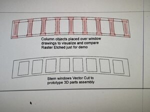
Next we move to the stern window openings themselves. In the upper drawing, I have taken the individual column drawings and placed them over the window drawing to visualize how they fit. This allows us to get a feel for things before we ever go to the laser. For demo purposes I have set the upper drawing to 0.5pt line width so the whole thing with Raster Etch.

The bottom drawing is the actual window openings themselves. This drawing is set to a line width of hairline so the entire thing will Vector Cut.

IMG_0287.jpg

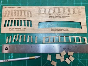
I used an 1/8" piece of cherry for this exercise. You see the results below after the laser has finished it's job. This took about 3 minutes. The upper examples are for visual reference while the lower examples are the actual parts we will assemble.

IMG_0289.jpg

Next, we punch out the parts to prepare for assembly. This is the point where kit builders get involved!! But remember, this is NOT a kit. It is an experimental prototype. Before it could go into a kit, it would need to be assembled, inspected, flaws noted, corrections made, drawings updated, more prototypes fabricated, more assemblies done, and repeat... until perfect.

IMG_0290.jpg

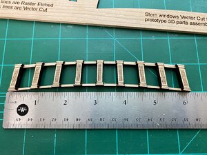
Now we glue the columns into position between the window openings. Notice how the curve of the tops and bottoms of the columns perfectly match the arc of the window frame. That is the beauty of CAD design.

IMG_0291.jpg

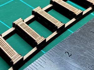
On closer inspection we can see the full 3D affect of the assembly. And this is just a very simple demonstration. Also notice the laser char on the inside edges of the parts. Personally, I like this on certain pieces as it adds a sense of depth to the part. But not in all cases... and of course we would need to carefully sand away that char which is extremely tedious on small parts. You will also note the columns are square/blocky shape where the original HMS Alfred had rounded columns. This shows the limitations of laser cutting. To overcome these issues, we would need to carve the columns with the CNC machine (or hand shape them). We will get to that in a future post. But first, let's continue with the Alfred for a while and see if we can fabricate some interior window frames.

Questions, comments, and feedback are always welcome!!

IMG_0292.jpg
 
Back
Top