• Ships of Scale has incorportated an extra level of security when you log In. Please follow on-screen prompts to acknowledge that you are not a robot via a "Check Box" or a "Pictorial Check Box Puzzle". This is needed due to higher level of AI Activity Security.
  • SUBSCRIBE TO SHIPS IN SCALE TODAY!

    The beloved Ships in Scale Magazine is back and charting a new course for 2026!
    Discover new skills, new techniques, and new inspirations in every issue.

    NOTE THAT OUR NEXT ISSUE WILL BE July/August 2026
  • Win a Free Custom Engraved Brass Coin!!!
    As a way to introduce our brass coins to the community, we will raffle off a free coin during the month of August. Follow link ABOVE for instructions for entering.

The Bounty Build from Plans and Partial Kit from the Lumber yard for Model Shipwrights by Gary

Back to the Framing:
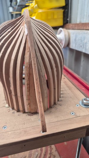
Finished the bow (Forward) framing
20260314_145605.jpg
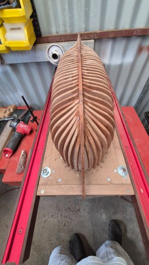
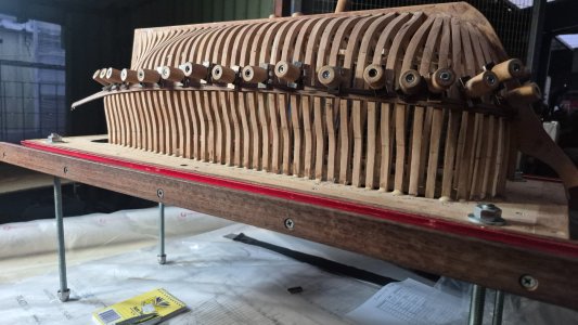
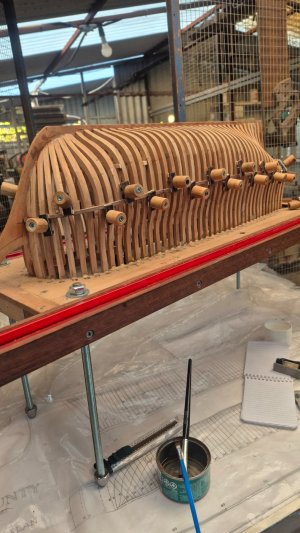
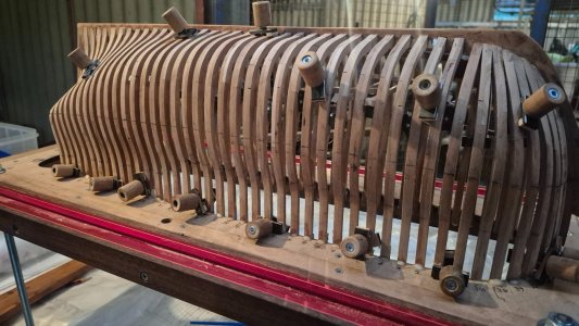
Now started sanding the frames. I have only had to add wood to 3 frames, and that did not take long. Maybe the gear I have is spot on for this type of work.
One thing I had on my mind was that it is better to build up the few frames than sand down to these skinny frames, because when I initially made the frames, I followed the paper lines pasted onto the actual "Bare" frame material. As you can see, it doesn't take much for a frame to be slightly out. In this pic above, with good observation, there are a few showing to be a little undersized.
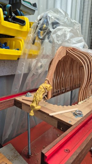
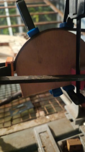
Next picture, I have the figurehead, although way oversize, placed on the Bow:
20260305_131504.jpg
I decided to have one made at this size as I am going to make an enlarged bow stem and then paint the figurehead ( with the right colours) and mount it.
 
Last edited:
Transom and Bow work
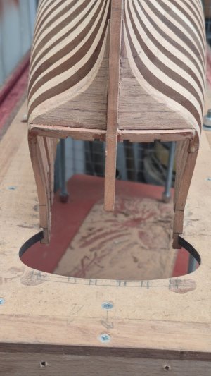
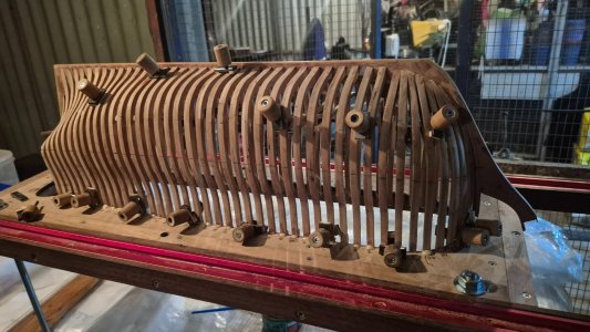
Finished putting on the framework at the Bow stem and also the filling on the transom.
20260325_091946.jpg20260325_091810.jpg
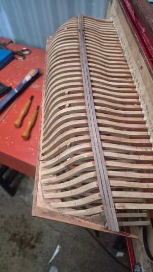
You may see I have started sanding the Starboard side of the frames. Hard on the fingers, but getting there.

* I was quite impressed with the accuracy between the frame heights, where only three frames on the Starboard side, I thought I had better build up, but I think I could have gotten away with sanding down just a touch more.
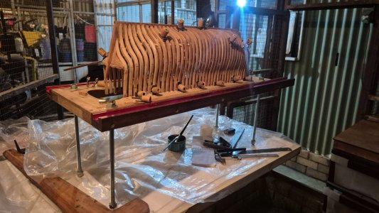
From the Starboard side to the Port side framing, being the same, I will be checking all distances of the frame on the Port side from the centre line of the ship at the main points on the frame, individually, from the starboard side sanded frames, if that makes sense. I will be using an engineer's scribing block to do this check.
To check the shape of the frames longitudinally, I use a piece of 3mm-thick by 5 mm-wide PVC strip, and it works a treat!
 
Last edited:
Thanks for the "Like," Corsair.
Thanks also, Grant.
Thank you to all who have visited, and hope you keep on visiting. Cheers Beer
 
Last edited:
SHOPPING
Have been progressing slowly forward on the sanding as I have a lot of trouble with sore wrists and fingers.
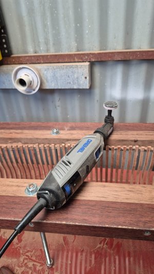
To rest my hands, I go off and look at ways to lessen the pressure on my hands and wrist. Of course, they do cost money, and inevitably, I would have had to eventually buy one. Dave Stevens mentioned a right-angle tool for a Dremel, but I did not have a Dremel, but a Ryobi high-speed rotary tool. They are just about as good as, if not the same as, a Dremel, but the right-angle tool did not fit it, unfortunately. Therefore, I had to go shopping.
Before I rushed out and bought a Dremel, I did a bit of Internet search and found out that not all Dremels can handle the right-angle tool effortlessly.
The Dremel 4250 175-watt motor is the one to use for the right-angle tool because of the drag on the motor due to the extra forces created by the extra gearing, etc. Coupled with an emery disk on the end takes a lot of power for the Dremel, and not losing power is a main concern. I have made the right choice and am happy with the choice of Dremel to drive the tooling.
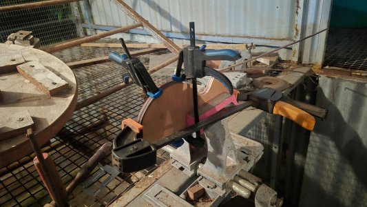
BTW, the disk on the end is my homemade sanding disk bit and works a treat
I must add, if it wasn't for the SOS site, and many other clubs or forums we may belong to, how would we find out if this tooling is available? It could take years searching on the net, and maybe looking at something different, as experience tells us that the item may not be good enough to do the job, and yet, like I have found out, there is a tool that I frowned on that actually is very capable of doing what I want it to do as the make has responded and made a stronger, more powerful rotary tool, capable to handle what I wanted to do. :)
20260407_172910.jpg

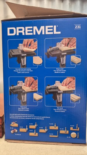
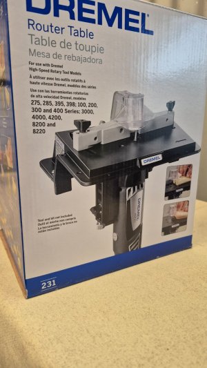
While I was in the mood for spending money, I saw a Dremel router bench and had had in my mind how I could make decorative wooden pieces, and the way I could go about it has been sitting in my mind for quite a long time. Well, on the board in front of me, at the tool shop, was a set of Router bits, which would be mainly the ones I may use in doing little rounded edges, coves, and so on.
Router bits that fit the Dremel:
20260407_173101.jpg
The Router bits are on the bottom of the box, with the numbers corresponding to the bit you may want.
The only criticism I have so far with this package is that it shows what router bits can do, but not on small bits of wood. The pieces they are gnawing at would be routed on a big router. It is what it is, I guess. Also, the shield is a problem as we know the dust will block the viewing, as well as sawdust sticking to the perspex. Always wear safety glasses/ goggles when routing.
20260407_173049.jpg
How much do you need to sand back to make the smooth transition from frame to frame? Do you need to go right to the bottom?
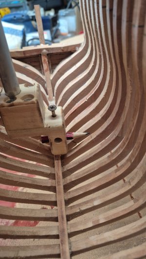
That depends on what you are doing; a fully enclosed model does not need to be done, but where there are decks, etc., going to be, yes, they must have a smooth transition. So how do I mark out where I go, dangle a rule over the edge into the hull, and scratch a line with a pencil where I need to sand the transition, or make a measuring tool and make it look like a craftsman put the transition in with some accuracy?
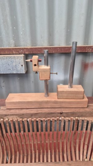
Well, I took the second option and made a tool and then another tool so I could measure on the outside and inside of the ship.
20260407_165725.jpg
Looks like a bit of Junk Art, but truly, they are very handy measuring devices.
The long block is used for measuring inside the hull. It is easy to set up. Place the pencil at a height from a flat surface, minus the width of the block, to get very close measurements each time. Of course, a supply of sharp, short pencils is always needed, as the pencil goes dull.
Then place it inside the hull of the boat after the extra calcs have been done, and scribe the lines:
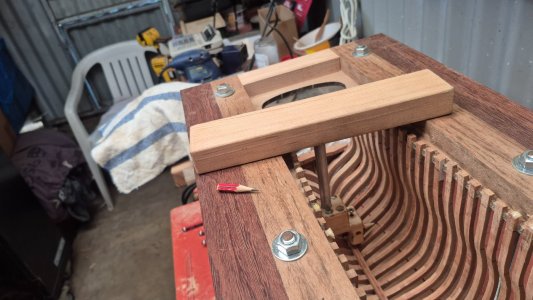
20260407_165950.jpg
20260407_165912.jpg

The smaller measuring block stand is used for the hull's outside measurements. The step-down is useful here as I have to make some very low measurements. The scribing head is universal, as it is used on each measuring block:
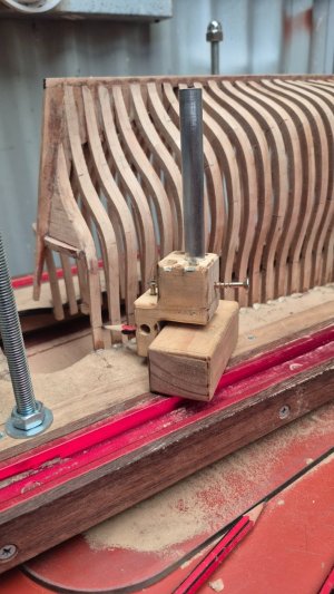
20260407_170513.jpg
The rod is a bit of a hollow aluminium shaft I had saved for a rainy day.:rolleyes::);)
 
Last edited:
The time has come for me to start to do the planking on this ship, well, the lower deck at least.
So the wood supplied needed to be thinned to the right thickness. Of course, this involves a sanding machine capable of sanding small pieces of wood.
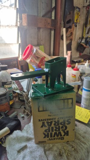
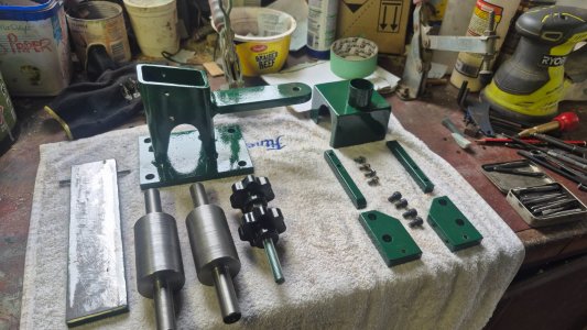
I had thought of purchasing a Byrnes sander (the Ants pants of the Model Ship World), but due to the lack of supply and the cost of having it sent over, it was totally prohibitive for my pocket, so I made my own:
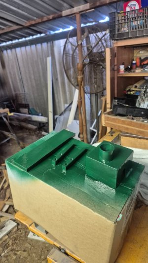
The first 3 pics show the parts all painted and ready to be put together:
20260612_082937.jpg 20260612_082954.jpg 20260613_102729.jpg
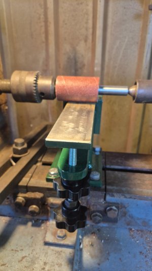
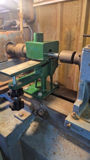
Then, after gluing the emery tape (80 and 120 grit) with cloth backing to the rollers, I set the roller to run parallel to the adjusting table on the stand. ( Gap between the roller and adjusting table has to be the same the whole length).
You will see I have offset the roller to run on one side of the roller, as the width of the adjusting table is only 50mm wide. The reason I did this is that I was not sure how far the emery cloth would be able to fit the roller on the recommended angle, which I thought should be correct. (It worked out fine!) Anyway, the roller has the same-sized and also length shaft on either side and can be turned around end-to-end and installed again, so the unused emery cloth can be used.
I did make another roller up just in case I need to use a finer grit, but so far, there has been no need to use finer grit as the 80-grit is working quite well or smooth enough for the planks, I feel. I will test-treat a plank piece to see the effect it leaves.
20260613_131537.jpg
Here is the completed "Chip maker".
It works an absolute treat20260613_132223.jpg

If you want to watch this 20-minute video on YouTube, I made. here is the URL :
 
Making Special Clamps for Planking and also Carving the Rabbet for the Garboard Strake:
I seem to be really travelling at a snail's pace, but it's about the available time, I must add. Retirement is supposed to say, relax, as you work day has been done. In this camp, it has, and it has not. Always something being done other than what I want to do..
Anyway, I have started putting in the lowest deck (skuttle deck?) and then fitted the wale and started planking the inside and prepping the rabbet for the Garboard Strake. I think now, fitting the lower deck frames may be a mistake as it interferes with the transition of the strakes. I may take them out. Does anyone say differently?

Fitting the Wales using special clamps called "barnacle" clamps
20260715_164751.jpg

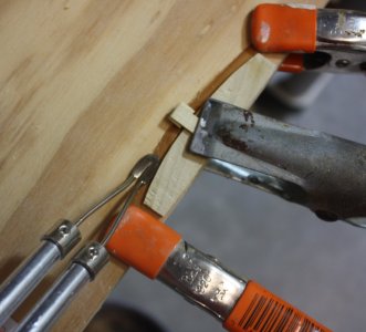
I have searched the net for different methods when clamping the planks to the frame, especially plank-on-frame models, and I came across Kevin Kenny's method he uses where the normal clamps won't reach, and I thought it was quite a good method to tighten the planks tight against the framework. I used them to fit the wale beams to the ship frame, and they worked a treat. One of the benefits of this type of clamp is you can back off slightly the pressure and let nature take its course, as the plank just moves away slightly, so the glue can run down between the plank and frame and then tighten afterwards. Never had to excessively tighten the plank to the frame either. With the Wales, I used hot water to make them flexible where they needed to be flexible, and that worked very well indeed. With the wales, I used full-length planks from the Bow to the Stern. This is against the grain in my build as I am trying to create how she would have been built. I will do some cheating to correct this, unfortunately. Anyway, let's have a look at the Barnacle Clamps just to get an idea why i call them barnacle clamps:
20260716_165058.jpg
At first, I started to clamp them by clamping from one side. After thinking about it, I changed half of the clamps over to the underside to receive a better clamping method;
20260715_164733.jpg
Anyway, you can probably gather how I gave them the name Barnacle clamps. ;)
With these clamps, it was quite an easy method to carry out clamping. As each plank dried, I loosened each clamp and either moved it higher up or down out of the way. No need to undo them or remove them completely.
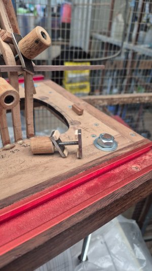
Going up to the first pic, there is the clamp/s I made, and there is a threaded bit of plate and also one unthreaded as well per clamp. Each piece has two pieces of wood barriers glued with CA glue to them. Each piece of the steel clamp barriers (wood bits)is of a different size. The reason is quite simply that I can set the plate to clamp properly as per the rules of clamping. If you want the rules of clamping, just hollow out and I will give them to you. Also, with these clamps, and if I am smart enough:rolleyes:, I will be able to do the internal (ceiling) planking, and also the external planking as one; slow, but methodical is the way I would think. Another good point about the clamp bars is that the length can vary at times, I can imagine, and also the angle could change. As I already found out, making longer clamps or slightly angled offsets is not a problem as well, just to get that perfect clamp position. Thanks, Kevin Kenny, for the initial idea. Thumbsup
As everyone does, they make a bending jig to get the right flexibility in the planks;
20260715_180826.jpg
Here showing the wales fitted with a graceful following along the correct position as according to the plans:
20260726_074302.jpg
I did make a mistake by not following my protocol and getting the little gap between the planks. It is annoying, but more speed, less haste- I should have used that here!
Also in this pic, you may be able to pick up my carving effort to place the rabbet in for the garboard strake and subsequent planks in as well to give them the tapered-off effect on each plank.
Garboard strake and subsequent planks to be fitted coming up. I do know that how these planks come out will be a reflection of my skill?? at fitting the strakes perfectly. This model of the Bounty is not going to have a copper bottom as is required, as I am not going to do that in this model. I am going to only plank the hull but use a wood that has a colour about it that sort of reflects the colours of copper. That wood I am going to use is called Tasmanian Myrtle. Fingers are crossed ...


20260715_173851.jpg

20260715_180655.jpg

20260715_180725.jpg

20260715_180922.jpg
 
Looking at the straight sticks of planking I am guessing you will not be spiling the hull planking. The second to last photo looks like an interesting system for broad bending the tapered planks. What are you using for pre-shaping the edge bend to prevent lift? It is easier to do after the breadth is shaped across the entire length of the plank,
Thanks
Allan
 
Looking at the straight sticks of planking I am guessing you will not be spiling the hull planking. The second to last photo looks like an interesting system for broad bending the tapered planks. What are you using for pre-shaping the edge bend to prevent lift? It is easier to do after the breadth is shaped across the entire length of the plank,
Thanks
Allan
Hi Allan, I think I understand you be saying how am I going to shape the end pieces to fit the bow and follow the twist of the shape of the ship hull? What I do is make a pattern up to match the curve of the hull at the bow end for instance and then shape the piece to fit the space. I then place the strakes in hot water and then I clamp using my "barnacles" to the shape of the area the piece is to be fitted, and after they dry, I then clamp after gluing using CA. With the barnacles I did mention how I can back of the clamp off to allow the plank to spring back slightly and then apply the CA, then tightened the Barnacle.
Is that what you mean?
After doing the typical keel Garboard Strake planks and the slightly thicker planks at the Wale, I will then divide the remaining areas.
Any help is most appreciative. Any comments most welcomed.
Thanks for viewing
 
Picture and a thousand words.... :)
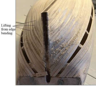
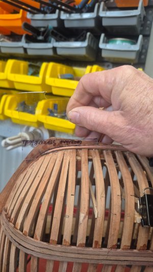
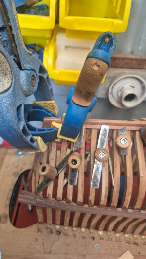
Edge bending around a form shaped for each strake same as if spiling the plank.
This photo is old, as I have found a hot air gun from the hardware store is much easier to use, will not scorch the wood, and is faster.
1785151634354.jpeg

If this is not done, the planks will lift and not lay flat on the frames or bulkheads. It is even more of a problem at the bow.

1785151784634.jpeg
Have you studied the four part video on laying out and planking posted several times here at SoS? Just in case.,
Part one of four:
 
Last edited:
Picture and a thousand words.... :)
Edge bending around a form shaped for each strake same as if spiling the plank.
This photo is old, as I have found a hot air gun from the hardware store is much easier to use, will not scorch the wood, and is faster.
View attachment 621987

If this is not done, the planks will lift and not lay flat on the frames or bulkheads. It is even more of a problem at the bow.

View attachment 621988
Have you studied the four part video on laying out and planking posted several times here at SoS? Just in case.,
Part one of four:
Thanks, Allan. I will take a look.
I used hot water, but that can be problematic when the plank is dry; the wood is a bit rough, as I had figured from previous efforts.
The heat gun sounds alright; do you use the heat while the plank is in situ? Sounds like that is extremely problematic also, as I can imagine the heat getting at the frames and structure. Would a hair dryer be as good or not hot enough?
As you say, lifting on the edges is a huge problem. I saw that on a plank for the garboard strake at the stern where it twists into the rabbeted section. It won't sit down completely as the wood is still not flexible enough.
Must add when I've done the Wales. Had no problem, but made a little mistake where I did not get the end of the strake fitting in tight on one plank on the end. Sits out like a dog's balls :oops:
 
Hi Allan, I had a look at the series of plank-bending videos, and you know what, only a month ago I watched all this guy's videos. My memory is slipping lots LOL, and yes, I now understand what I needed to do. So, to let you in on my progress on the Garboard strake. At the bow end, I did think about how I would fit the garboard strake at this point, and the reading says, "You should not go too far forward toward the Bow." So, armed with this knowledge from this seemingly useless book called "Planking Techniques for Model Ship Builders", by Donald Dressel, I at least tried to understand the "Distance Needed" and what he may have been talking about, and sort of fathom out what he may be trying to communicate through his wording.
So what I did was lay the plank ( which are now only 5" long), scaling to the length of the planks that were used to cut the planks to, back in the day, and it fits nicely halfway along between the centre lines between the frames of the ship. I laid down a piece of thin but substantial piece of plastic ( plastic sheeting used on a shirt box thickness to give you an idea) and formed the shape the wood had to be by laying the plank against the keel and then marking the three points on the plank where I needed to, and then shaped it to fit. So this gave me a perfectly straight edge. Maybe a photo says it better, so I will take one. BTW, I am holding the pattern on its edge (Vertical) as it's the only way to take a photo using one hand and a finger on my phone, as the template was laid flat on the plank and then marked for shaping ;
20260728_081519.jpg
Maybe you can see the plastic strip with the marking on it, shaped to where I have shaped the plank now? The plank is pointed but not a reduced plank-width cut, so that is allowed. The trailing edge was not shaped, so I retain the straight edge.
Also, I have that slight gap problem between the planks on the plank that I did not think about too much at the time, but another glaring mistake that I am well aware of before I started fitting the wale planks. This was due to failing light and my keenness to fit the planks.
The next pic shows the stern fitting of the plank, and not going to plan. Left this off last night as I am a bit lost on how to do this correctly and have a good view of what I am doing. In the end, be able to place this twisted plank and fit it correctly to where it has to sit. Don't laugh, as I don't know if this has worked, as I just done yesterday evening;
20260728_081733.jpg** The steel clamp bars have pieces of wood glued to the ends, which don't show up in the pic!

Hmm, I will remove it to check its location soon. It is one of those complex bends that the guy was referring to, and I may have to bend it sideways, as shown in the video, but not much.
Make sure you read my first entry above, Allan, so you get an idea of how I am mucking this up.
 
Hi Gary

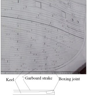
Regarding the garboard, as a rule of thumb I have always ended it at the forward edge of the boxing joint like on the actual ships. This can be seen on the planking expansion drawings like the one below of Squirrel (24) 1785. Hope this helps.

View attachment 622326
Hi Allan, yes, that appears to be where mine does finish too. :) Beside that, this is where it must finish also, other wise too far further forwards will cause out of a alignment of the strake, which will cause huge problems further on as the next planks having to be fitted with a kink, not a straight line to follow. I think the information is out there but a bit of common-sense must prevail in the logic of the build and when this information you can look at, at times means no sense until you do the fitting and then it dawns on you.
By the way, I made up the bending jig as per video and put a kink in the wood and it worked magic. Virtually it fitted like a glove!. I will need it for the next one after the Garboard Strake also and that strake is smaller and slightly thinner. Apparently I can blend the thickness transition from one strake to the next and I hope to do that by scrapping the wood to match. Before I do that I will run the ceiling strakes internally at the same time so I can use the barnacle clamps both sides as this should save time trying to find methods of clamping than using thumbnails. I am at a quandary to either doing a static build without seeing the internals or doing it to have a removal section to show the internals partially. I want to leave that open to my latter on thinking and if I don't, then I have had some practise at setting the internals also.
 
Last edited:
By the way, I made up the bending jig as per video and put a kink in the wood and it worked magic.
Congrats! It is a moden day variation of spiling and for me, easier to cut straight planks, narrow the breadth per the marked out hull, then edge bend. I prefer to soak the planks for a few hours then bend around the form. clamp it down and then heat it until dry. I gave up using her hair dryer for good reasons and spent US$20 at the local hardware store for an industrial grade with variable temp settings. The hotter the better but not enough to scorch the wood as it dries. Experiment with what works best for you.

Allan
 
Congrats! It is a moden day variation of spiling and for me, easier to cut straight planks, narrow the breadth per the marked out hull, then edge bend. I prefer to soak the planks for a few hours then bend around the form. clamp it down and then heat it until dry. I gave up using her hair dryer for good reasons and spent US$20 at the local hardware store for an industrial grade with variable temp settings. The hotter the better but not enough to scorch the wood as it dries. Experiment with what works best for you.

Allan
Allan, I have a long way to go and learning how to navigate the hurdles and your help/ ideas, and anyone's help is invaluable. Guess I better go buy a Heating gun with variable settings.
 
Back
Top