- Joined
- Jan 24, 2021
- Messages
- 10
- Points
- 13

If you missed my intro thread, Dave was kind enough to invite me to start a build log of this project so here goes.
To begin with a bit of background. Since I was a small kid I've been into tall ships and everything that goes along with them, especially high seas piracy but, as an artist, my interest was mainly aesthetic. I love the way everything looked back then but as to knowledge of maritime history, sorry no, haven't a clue about any of it. So I come off the back of bingewatching Black Sails for the third time in as many years and I'm inspired to model something awesome like that. I know some of the guys who worked on that show and jealous doesn't even begin to describe what I'm feeling!
So that's where I am- I know what I like but I have no idea what all the bits are even called. The Crimson Spanker is going to be my very own pirate ship. It'll double as my office in VR, where I expect to be holding most of my meetings a couple of years from now. The ship design is going to be more along the lines of what I think is cool, rather than an accurate rendition of any specific ship that ever existed but it still has to be "realistic" for a given definition of such. What I mean is that I want this ship to be something that could have existed back in the day. I know enough engineering to know that there's always more than one way to skin a cat so I'm assuming there were as many hull shapes and mast constructions as there were shipbuilders but I do want it to be constructed using techniques that are at least similar to the kinds that were available then. If there are commonalities that apply to all ships then I want to share those, rather than just look weird like nothing that ever existed before. Something that, to a better trained eye than mine, looks like it could have sailed.
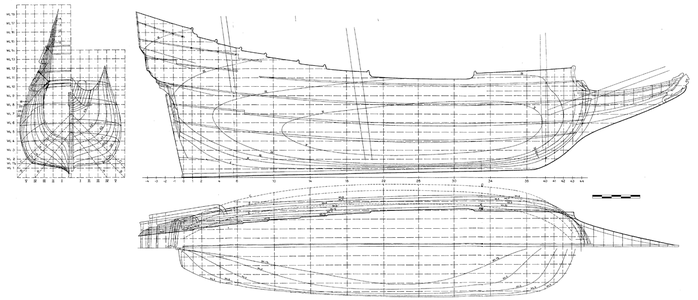
So I started by scouring google images for references. Found a lot of plans and settled on one for the hull shape and another for the masts
![TableA [1600x1200].jpg TableA [1600x1200].jpg](https://shipsofscale.com/sosforums/data/attachments/192/192393-eceec721150bf7c05f9375891100189e.jpg?hash=7O7HIRUL98)
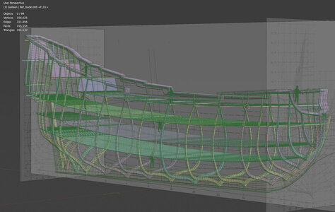
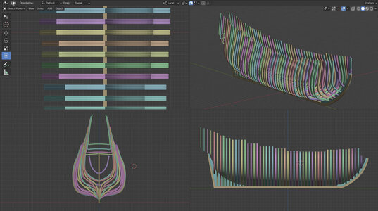
and I jumped into Blender to get some geometry down just as a starting position. First mistake I think, when I was looking at the side elevation there were vertical lines every 1m from the stern until they increased to every 2m for a bit then back to 1 again at the bow. I (wrongly?) assumed these were where the rib-beams were positioned and used the corresponding numbered profiles on the end elevation to put a bunch of single ribs in, tapering from about a foot square at the bottom, to 8inch at the top. Looking at some posts on this forum it looks more like there was that much wood running up there that it was practically a solid wall of timber?

Next up was the masts. I looked around the web and from what I could tell they all seem to be variations on a theme, the main difference being how many stages (tops?) they had going up the way. I plumped for the USS Constitution but couldn't read exactly what was going on with the top part of the main mast but I could see from photos that most of these seemed to be squared off in one fashion or another so I just kinda fudged roughly how I thought it could have been done. I then cloned a slightly smaller one for fore and a tad smaller again for the mizzen. From what I could make out from photos some ships had one or more masts angled backward and the rest seemed more or less vertical. I don't know what the thinking was behind this but I like the swept back look on the mizzen mast so I angled that back more or less just for the hell of it.
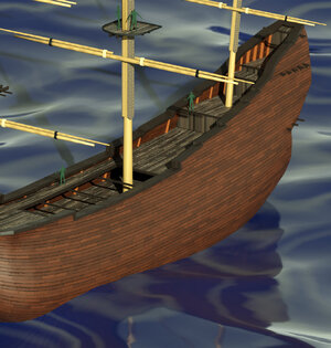
So that's where I am for now. Nothing that could be considered final geometry, just placeholders indicating approximate shape and proportions. Any input much appreciated at this point, especially as to what my options are for the rib framing. I lobbed some cheap and nasty textures on just to get a rough idea of what I'm looking at and fired off a render. Happy enough with where it is for now but itching to start fleshing out the final design and then getting to work on the modelling proper. Still no idea what I'm going to do on the stern yet. Or the bow for that matter. There seem to be an awful lot of options out there.
To begin with a bit of background. Since I was a small kid I've been into tall ships and everything that goes along with them, especially high seas piracy but, as an artist, my interest was mainly aesthetic. I love the way everything looked back then but as to knowledge of maritime history, sorry no, haven't a clue about any of it. So I come off the back of bingewatching Black Sails for the third time in as many years and I'm inspired to model something awesome like that. I know some of the guys who worked on that show and jealous doesn't even begin to describe what I'm feeling!
So that's where I am- I know what I like but I have no idea what all the bits are even called. The Crimson Spanker is going to be my very own pirate ship. It'll double as my office in VR, where I expect to be holding most of my meetings a couple of years from now. The ship design is going to be more along the lines of what I think is cool, rather than an accurate rendition of any specific ship that ever existed but it still has to be "realistic" for a given definition of such. What I mean is that I want this ship to be something that could have existed back in the day. I know enough engineering to know that there's always more than one way to skin a cat so I'm assuming there were as many hull shapes and mast constructions as there were shipbuilders but I do want it to be constructed using techniques that are at least similar to the kinds that were available then. If there are commonalities that apply to all ships then I want to share those, rather than just look weird like nothing that ever existed before. Something that, to a better trained eye than mine, looks like it could have sailed.
So I started by scouring google images for references. Found a lot of plans and settled on one for the hull shape and another for the masts

![TableA [1600x1200].jpg TableA [1600x1200].jpg](https://shipsofscale.com/sosforums/data/attachments/192/192393-eceec721150bf7c05f9375891100189e.jpg?hash=7O7HIRUL98)
and I jumped into Blender to get some geometry down just as a starting position. First mistake I think, when I was looking at the side elevation there were vertical lines every 1m from the stern until they increased to every 2m for a bit then back to 1 again at the bow. I (wrongly?) assumed these were where the rib-beams were positioned and used the corresponding numbered profiles on the end elevation to put a bunch of single ribs in, tapering from about a foot square at the bottom, to 8inch at the top. Looking at some posts on this forum it looks more like there was that much wood running up there that it was practically a solid wall of timber?

Next up was the masts. I looked around the web and from what I could tell they all seem to be variations on a theme, the main difference being how many stages (tops?) they had going up the way. I plumped for the USS Constitution but couldn't read exactly what was going on with the top part of the main mast but I could see from photos that most of these seemed to be squared off in one fashion or another so I just kinda fudged roughly how I thought it could have been done. I then cloned a slightly smaller one for fore and a tad smaller again for the mizzen. From what I could make out from photos some ships had one or more masts angled backward and the rest seemed more or less vertical. I don't know what the thinking was behind this but I like the swept back look on the mizzen mast so I angled that back more or less just for the hell of it.
So that's where I am for now. Nothing that could be considered final geometry, just placeholders indicating approximate shape and proportions. Any input much appreciated at this point, especially as to what my options are for the rib framing. I lobbed some cheap and nasty textures on just to get a rough idea of what I'm looking at and fired off a render. Happy enough with where it is for now but itching to start fleshing out the final design and then getting to work on the modelling proper. Still no idea what I'm going to do on the stern yet. Or the bow for that matter. There seem to be an awful lot of options out there.


