• Ships of Scale has incorportated an extra level of security when you log In. Please follow on-screen prompts to acknowledge that you are not a robot via a "Check Box" or a "Pictorial Check Box Puzzle". This is needed due to higher level of AI Activity Security.
  • SUBSCRIBE TO SHIPS IN SCALE TODAY!

    The beloved Ships in Scale Magazine is back and charting a new course for 2026!
    Discover new skills, new techniques, and new inspirations in every issue.

    NOTE THAT OUR NEXT ISSUE WILL BE July/August 2026
  • Win a Free Custom Engraved Brass Coin!!!
    As a way to introduce our brass coins to the community, we will raffle off a free coin during the month of August. Follow link ABOVE for instructions for entering.

The GRACIE S - a POF Model

Joined
Oct 2, 2025
Messages
587
Points
198

The GRACIE S - a POF Model

Classroom 2 MWF - evening EST - short presentations

Featuring: The Station Section Method

A framing method that I have been developing over the last 20 years.

This class will only cover the framing portion of building a model of Gracie S.


Gracie S
San Francisco pilot schooner 1893
95.5' x 83' x24'7" x 19'7" 91t

Stations 52" intervals

R&S 26"
Frames 8" as a paired bend 16"
Space 10"

The model is 1:48 scale.
frames 0.17" Black Cherry Prunus serotina
spaces 0.21" Pine 2x4 Home Depot aisle special
space tops 0.21" Yellow Poplar Liriodendron tulipifera

Gracie S is a small vessel. It was designed for speed with no provision for it being a cargo carrier.
It looks fast, sleek, but a bit hippy.
 
The Station Section Method

First I will describe concept behind this POF method and its advantages.
My first scratch build was Kate Cory, plans by Eric A.R.Ronnberg Jr.., 1/4":1'.
I used the Hahn method. It is an excellent first scratch POF method to learn from. Hahn was building at 1/8":1' scale in his presentation. At this scale the waste of framing stock is insignificant. At 1/4" scale the wood is eight times the volume and the loss to waste is noticeable. For a skills development project the loss is acceptable if domestic species of wood is used. I lofted each frame by hand on vellum. The process was very time consuming, tedious, and frustrating. I found that I cannot plot acceptable curves. An easier lofting method became a priority.
Doing the frames as scale appropriate individual timbers was also a priority. Drawing and building each bend as an isolate unit became something to avoid. On a large ship, this can involve drawing up to 200 or more individual frame shapes.

After many starts and stops I have developed a method that works for me. I have tried different names - station sandwich method is one - but right now Station Section Method is my choice.

On lines plans of a ship, the shape for each station is already on the plan. There are usually between 20 and 30 individual shapes. No plotting is necessary.
This means that all of the frames between two stations must be built as a stack, as a unit, as a section. That is: if having to plot points and draw 200 to 300 new curves is to be avoided, the station shapes have to stand for their associated frames. The actual shape of most of the frames is determined by how the wood itself is shaped.
My reading indicates that the 1670's era Navy Board framing was done as sections. Even more significant is the probability that the mold loft only chalked the frame shape at each station on the floor and only made patterns for the timbers of each station. The patterns had marks - sirmarks - for each of the frames between each station. The shipwrights in the yard did the interpolation.

There needs to be a way to align the frames in each section. The two frames in a bend have very little area inside the frame that allows for a perpendicular line to be inside the two frames for most of the hull. This means that there is zero chance that a whole section of frames can be aligned using the inside bodies. A common alignment that is outside the frames has no limitations. It just means that there is more wood to remove when shaping. By having precise multiple alignment points there is an identical pattern in precise alignment at each end of a stack of frames (station section).

The locator points to mate the common faces for two sequential station sections are easily within the body of the frame. There is a limit on how deep a hole can be drilled without exiting the frame and marring the outside or inside face,

I also include temporary filling timbers in the spaces. I use construction Pine for this. It is low cost and easy to work. The frames in each section are more stable and shaping is much easier. The hull is a solid surface for shaping, faring, and sanding. It is not like trying to smooth a picket fence or bumping along rail road track ties. The frames cannot move while being abused.
The framing style is not limited -- or constrained by this method.
Some of the possibilities to be shown on Monday.
 
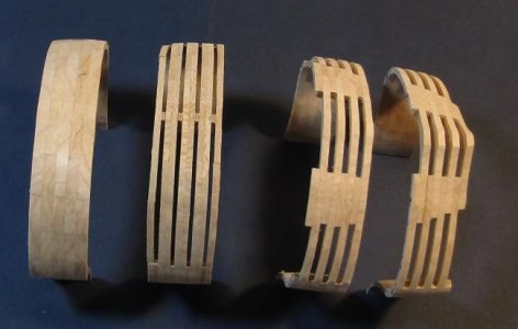
photo # 000000 framing styles 2.jpg

Far left is a solid wall of frames

Next is a common North American and French style - a bend and a space - in the example with width of the space is the same as a frame. (The small piece of wood in the middle of each space is the deadwood. It goes from the top of the keel to the underside of the keelson. I believe the it was present in most if not all RN ships in the wood era. There would be a 1 inch high "window" close to the keel. The bilge water had to be able to flow between port and stb.) ( This is the part that I neglected to include when I framed this vessel. The result more than adequately demonstrated why it was a mistake not to include it.)

Second from right is my preferred styled framing. Navall timber framing is a complete frame alternating with a partial space. A short futtock 1 (Navall timber) overlaps the butt of the floor and futtock 2 -and probably what was part of futtock 4. The overlap forms a solid band of timber that resembles the band of Navy Board framing, This band mimics two proof diagonals. The diagonals give proof to the nature of shape of the hull.

The far right is Navy Board framing - late 17thC. Stylized by being regular. It is actually the way hulls were framed from just after frame first building replaced shell first. Many of the famous Navy Board models from the 1670's era are this style.

The frames in the example are made using Hard Maple. If the grain looks large relative to the size of the frames, that is because the scale is 1:120.


photo #0000-Beagle framing.jpg
(Marquardt - HMS Beagle)

It will also work for the complicated RN framing with bends and filling frames and timbers of different widths - sequentially narrower the higher. It just needs layers of cardboard added to the space filling timbers.

What it cannot do are cant frames. It would be significantly more difficult to include butt chocks.
Free standing single filling frames almost require butt chocks if using the current framing methods. Free standing single frames have unsupported end grain to end grain bonding. They may as well be dry butted for all the strength that any glue could provide. The Station Section method protects single frames during shaping and faring - by locking them in with the temp space filler Pine, so butt chocks are not needed.

My personal choices are to forego butt chocks, use square framing for the whole hull - no cant frames - and no single free standing frames.
With butt chocks - I do not see how to fit them into frames with a lot of bevel and they are all but invisible for anything but a section model.
Cant frames - except for CA Redwood dimensions I do not see that any species of tree could provide stock deep enough to allow square frames in the zone where the frames are canted for an actual ship.. At model scales, this is not a problem and I use stylized framing so I am not cheating.

The Station Section Method does not use a baseboard. It uses no jigs. The keel - stem - sternpost - all go on after. There is one strict limitation. The framing stock must all have strict tolerances for stock thickness. Error creep is a constant hazard.

 
Last edited:
Back
Top