• Ships of Scale has incorportated an extra level of security when you log In. Please follow on-screen prompts to acknowledge that you are not a robot via a "Check Box" or a "Pictorial Check Box Puzzle". This is needed due to higher level of AI Activity Security.
  • SUBSCRIBE TO SHIPS IN SCALE TODAY!

    The beloved Ships in Scale Magazine is back and charting a new course for 2026!
    Discover new skills, new techniques, and new inspirations in every issue.

    NOTE THAT OUR NEXT ISSUE WILL BE July/August 2026
  • Win a Free Custom Engraved Brass Coin!!!
    As a way to introduce our brass coins to the community, we will raffle off a free coin during the month of August. Follow link ABOVE for instructions for entering.

USS Constitution 1797 by The Bitter End - 1/76.8 - 44 Gun Frigate - heavily modified kit

Mouldings:

The moulding position and profiles came about as the result of many a long discussion and evaluation of the usual sources.

This began with creation of the moulding by scraping pear strips with various profiles notched into the edge of a blade.

I then taped off the lines of the moulding to create a smooth reference line to run the gunwale moulding.

PXL_20260427_170750681.jpg


This was then thickened to reflect the heaver bulwark seen in the hull model.

image.png


PXL_20260501_065603422.jpg


That feature was followed with the feature which would have essentially been a capping rail in the doughty plans and runs mid way up the spar deck gun ports

image.png


PXL_20260501_194123832.jpg


The final step was to install the small moulding above the thickening in this bulwark as seen, yet again, in hull.

image.png


This was achieved by glueing a strip of 0.6mm thread above the timber. This whole section will be painted black so the strange colour choices are not a problem. You will also notice that there is a cap rain in place. I was going to do a separate post for this but this is just a strip of timber with mouldings carved with the razor technique as for the other mouldings.

PXL_20260504_190928173.jpg


I also included the cap rail around the forecastle in this post as it was just a shaping to match the curve and bullnosing the edge. The very front of the bow was cut open later in the build.

PXL_20260506_125216534.jpg

TBE
 
Spar deck railings.

This feature doesnt really deserve a post of its own but it had to go somewhere so here it is.

I essentially just copied the gun port spacing of the doughty plans. The real decision to make here was how far forward the railings will go. The decision to leave the bow open was the result of alot of interpretation of the sources. I am however open to the idea that this may be totally wrong. Tyrone Martin seems to agree with the idea that the bow was open completely. As for planking there is a reference in the records of the Barbary wars where it is stated that the carpenters planked up the gangways up to the fore rigging. This is obviously conjecture but I would think different language would have been used if the bow was already planked instead of using the fore rigging as the reference for the limits of the planking work done.

image.png


dimensions of upright supports were decided based on looks alone....

PXL_20260510_073312819.jpg


The decision to leave a gap or not came from the corne 1803 painting where a gap is obvious...

image.png


The rest of the rail was just moulded and aligned to match the cap rail on the quarter galleries.

PXL_20260510_185758805.jpg


image.png


Things are still looking a bit scruffy but this will all be buffed up before painting.

TBE
 
Channels:


The channels were made using pear wood slabs cut to size and then chamfered back to create the slope seen on the underside of the channel.

Dimensions were made to match moulding dimensions seen on the Doughty plans

image.png


and the profile was taken from the Ware rendering of the Frigate United states:

image.png


The channels were then marked to indicate deadeye positions which were taken from the corne painting along with some reference to Eriksson in "all sails up and flying"

PXL_20260515_045211366.jpg


Once Ii was happy with all this the channels were notched to accommodate deadeyes and mouldings were secured to the outside of the channel before installation:

image.png


The final step for the channels was to add the channel moulding which can be seen below:

image.png


Channel positions were taken from Doughty with some slight modification from the corne positions. This was relatively simple besides me repeatedly sticking incorrect channels into incorrect positions. Not the best photo but it gives an idea of these positions.

image.png


TBE
 
Access stairs:

This minor feature caused me a huge amount of trouble. I decided follow the layout seen in the Roux paintings of the President and include the side boys. This interesting feature is a position used by sailors to assist less agile users in their ascent of the rungs.

image.png


To begin I used my plank clamp and cut mouldings into strips

PXL_20260524_074841729.jpg


These were then cut into shorter lengths and shaped:

PXL_20260524_080905465.jpg


To produce this result.

PXL_20260531_191848621.jpg


The very careful observer will notice that my scupper had to be moved and I made it too large when i replaced it. I also realised that I had included too many steps. The joys of scratch building without any real plans:

Below is the final version before paint. This was obviously repeated on both the other side.

PXL_20260601_063524837.jpg


TBE
 
I admire the quality and precision of craftsmanship in making this model. It is hardly achievable when using just hand tools. The generations ahead hopefully will discover this model and the scientific articles will never conclude at: "how they could have achieved this? This could not be without extraterrestrials involvement."
 
I admire the quality and precision of craftsmanship in making this model. It is hardly achievable when using just hand tools. The generations ahead hopefully will discover this model and the scientific articles will never conclude at: "how they could have achieved this? This could not be without extraterrestrials involvement."
Thank you YT! That a great thing to say! SUrely they will realise that you can achieve anything with sufficient slave labour ROTF
 
Gratings:

Purists avert your eyes!

It was at at this point in the build that I realised without buying a very expensive Milling machine or buying gratings I was unlikely to be able to generate visually appealing gratings at scale. I therefore decided it was time to buy a mini CNC machine for various tasks around the farm which could also be used to make the gratings for Constitution. This involved the simple task of learning fusion and importing a TTC 450 ultra. I have been very careful about not allowing myself to use it for anything else on the build so far and I hope to keep it this way. I mayyy use it for some of the block creation in the future but we shall see what happens.

The gratings themselves were fairly hard to research. David steel specifies that upper deck gratings should be 15 inches above the deck and that grating holes must be no bigger than 3 1/2 inches wide(apparently to prevent the heel of a shoe getting stuck in them??)

Positions were obtained from the Waldo deck plans.

I was not particularly strict about their appearance as they will be 99% covered by the Spar deck. I did however feel that it made sense to do some testing before creating the gratings which will be on the spar deck.

Step 1 was to draw out a series of protruding pins in a grid in fusion:

image.png


These were then cnc milled out into pear wood slabs....As you can see this process took several attempts to figure out.


PXL_20260627_135111358.jpg


PXL_20260627_151447115.jpg
o

This was then cut out and the slots were filled with thin pear strips:

PXL_20260627_170822841.jpg


These were then sanded flat. Much to my horror I realised that I had allowed the outer edge of the gratings to terminate in a protrusion on the port and starboard sides. I decided to accep this as it would essentially never be seen and was part of my learning process.

PXL_20260627_174652653.jpg


I then Glued the framing to a piece of 0.5mm sheet so that I could create a removable grating panel doing this in 2 pieces also allowed me to stain the frame of the grating using Hesse vintage oak stain without staining the grating:


PXL_20260904_053710094.jpg


This was then cut to shape, the grating was inserted and sanded to a curve. I suspect these protrude too far above the deck but I will address this when I get to the Spar deck where they can be more clearly seen.

PXL_20260904_104413374.jpg


Untitled.jpg


TBE
 
That technique using a mill instead of slitting blades was a new one for me too! Nicely done. Something to try on my current project with the time comes.
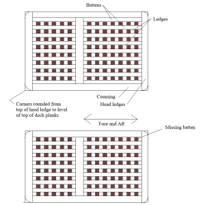
Keep in mind that the gratings did not have open sides. I find it much easier to make the grating first, then size the head ledges and coaming pieces around the grating.
Allan
1789908934055.png
 
That technique using a mill instead of slitting blades was a new one for me too! Nicely done. Something to try on my current project with the time comes.
Keep in mind that the gratings did not have open sides. I find it much easier to make the grating first, then size the head ledges and coaming pieces around the grating.
Allan
View attachment 637992
Hello Allan


This is a very handy sketch Thank you! This is the kind of detailed information I love

I will be sure to not allow the missing batten when I am doing the spar deck gratings where they are visible., this really brings home the importance of practicing before the main event.

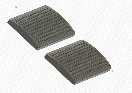
with your corners...do you mean they should look like one of these 2 options with battens on the perimeter as shown?

you can get a better look if you use this fusion link but the images may be sufficent https://a360.co/3SW9Kjz


1789911289998.png
 
Cable Bitts

This feature has not yet been installed but in the interests of not falling way behind on the log again I decided to show what was done. As usual @Marcus.K. and I discussed this feature at length and ultimately used the pook 1849 drawings.....


IMG-20260604-WA0162.jpg


and the beautiful constellation drawings for scale and design.


IMG-20260604-WA0163.jpg


The waldo deck plan was used for position. Drawing modification done my @Marcus.K.

IMG-20260604-WA0137.jpg


This was just a matter of cutting to size and shaping.

PXL_20260604_132922139.jpg


PXL_20260604_132911512.jpg


IMG-20260604-WA0286.jpg


There was a second set made which I dont have photos of at the moment. More on the subject will follow when I install the bitts
 
Cannon...Again

Purists look away...again

This portion of the Cannon, is just a quick reference to my approach to manufacture.

After tuning on the lathe and trying various options for repeatable cannon I decided to 3d Print the Cannon with my FDM printer. I realise that this goes a bit against the tradition of our hobby but I saw myself either producing an inferior quality product or buying the cannon from a supplier(which may have been difficult due to the fact that these were in fact abnormally short for a naval vessel). What i do think is in the spirit of the hobby is learning a new skill and pushing the limits of that skill. If anyone wants to print these cannon I am happy to provide the files and the settings for my printer which allowed this level of detail. They are not perfect but with a bit of cleaning up they should be acceptable. They are only 32mm in length so defects are exaggerated:


image.png.18bb8d22b365d9f529c634f990d1d881.png


PXL_20260804_163323637.thumb.jpg.4b1653afc2c820ff8a18ec5f54a01e09.jpg


PXL_20260804_075504432.thumb.jpg.d10832f94a8141c764ba1c32e21500be.jpg


I promise this is the last of the 3D printing for this model. I am trying to avoid buying anything for this build and this seemed like a reasonable compromise...forgive me!

Cheers

Haiko
 
Timberheads.

Nothing too exciting here. Just some timber heads copied directly from the doughty plans. There are more to come later in the build but I wanted to get these out the way. Several of them have already broken off since these photos were taken but I will replace them and pin them once I have finished the head timbers.

They were made using a series of jigs made for the sanding disc attached to my mini lathe and were churned out at speed.

PXL_20260816_174725677.jpg


Disregard this bollard timber. It was very much just a little trial

PXL_20260820_163152742.jpg
 
LIfeboat Davits

These little items are the second last of the stern features which form part of my build log backlog.

The davit dimensions were taken directly from the plans shown in Eriksens book - All sails up and flying.

WhatsApp Image 2026-09-20 at 16.52.41.jpeg


I decided however that the davits would be best placed ontop of the rails as the weight of the evidence points in this direction.


IMG-20260614-WA0116.jpg


IMG-20260614-WA0117.jpg


IMG-20260614-WA0118.jpg
IMG-20260614-WA0111.jpg


IMG-20260614-WA0112.jpg


IMG-20260614-WA0113.jpg


IMG-20260614-WA0114.jpg


They were easily made with a little shaping of pear stock. The exact dimensions may still cause me issues as I ultimately determine which of the ships boats will hang here. There are several options and the evidence is unclear. I will cover this issue when I get to it and give the ships boats a reasonable amount of attention.

PXL_20260614_125154845.jpg


Haiko
 
with your corners...do you mean they should look like one of these 2 options with battens on the perimeter as shown?
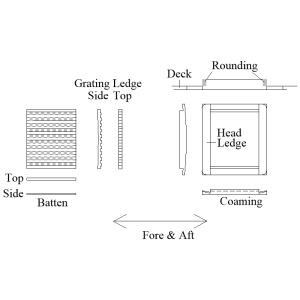
Picture and a thousand words. The rounding goes only from the top edge of the deck planking to the top of the head ledges. The sketch is not exact but should give you an idea of how it was. It is not difficult to do once the coamings and head ledges are assembled and before being set in place.
1789912644839.png
 
Picture and a thousand words. The rounding goes only from the top edge of the deck planking to the top of the head ledges. The sketch is not exact but should give you an idea of how it was. It is not difficult to do once the coamings and head ledges are assembled and before being set in place.
View attachment 637996
Thank you again Allan! This makes sense now. I blame sleep deprivation for my failure to understand. I Will definitely be applying this to the spar deck hatches.

Cheers

Haiko
 
Back
Top