-

Win a Free Custom Engraved Brass Coin!!!
As a way to introduce our brass coins to the community, we will raffle off a free coin during the month of August. Follow link ABOVE for instructions for entering.
You are using an out of date browser. It may not display this or other websites correctly.
You should upgrade or use an alternative browser.
You should upgrade or use an alternative browser.
- Traditional Windlass Designs:
On many 19th–20th century sailing vessels, the windlass axle (or barrel) rested in bearings either on the forward bitts or on a dedicated Samson post. These bearings were often cast iron or heavy hardwood cheeks with iron straps, bolted through for strength. - Sources for Drawings:
- Howard I. Chapelle’s books, such as “American Small Sailing Craft” and “Boatbuilding,” often include detailed windlass sketches.
- The Smithsonian Ship Plans collection sometimes has separate windlass plans for small craft.
- Model ship forums or archives like Mystic Seaport Museum sometimes have measured drawings available.
- Typical Mounting Details:
- The barrel turns in gudgeons (U-shaped iron brackets) bolted to the Samson post or bitts.
- The pawl rim and pawl posts are on the deck in front of the barrel to prevent backwinding.
- The handspikes or levers insert into sockets in the barrel or drumheads for manual operation.
- Joined
- Jun 29, 2024
- Messages
- 1,365
- Points
- 393

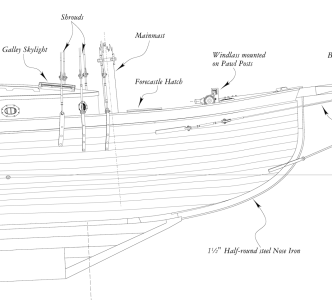
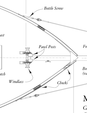
Your skipjack is a relatively small craft so the windlass was a a commercially manufactured item probably bought from a local ship chandler. Both drawings that you posted show what little mechanism that there was. The diagram that Jim posted shows the same thing.
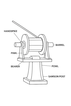
If you look at the drawing posted immediately above, there is a rectangle sticking out behind each of the windlass heads. This is a socket for inserting a hand spike. Within that semicircular shoe on the forward end of the socket there is a ratchet mechanism. This allows the hand spike to engage the sprocket attached to the Sampson post on the downstroke, and disengage from it on the upstroke. The external pawl also engages the sprocket to prevent it from rotating backwards.
The windlass on your skipjack drawing works on the same principle except the hand spike sockets are on the outboard ends of the windlass drums with the large sprocket and pawl separate.
All of these windlass designs would have been patented, many of which are posted on the internet.
Roger
The winder (a term from St. Michael's boatyard that I learned) boat yard drawings of a skipjack at the Smithsonian) has a frame on which it rests plus an A frame over top of it. As you are from Washington Crossing maybe consider a day trip to St. Michaels to see a full size skipjack. It's about 2.5 to 3 hour drive, but quite pleasant and the crab cakes at the Chesapeake Landing restaurant in St. Michaels are some the best we ever had. I hope they are as good today as they were back when we were there. I have no idea if the boat yard is doing any rebuilding right now, but when I went there many moons ago, they let me take a good size piece of an old keel that was being replaced which I used for building two skipjack models.
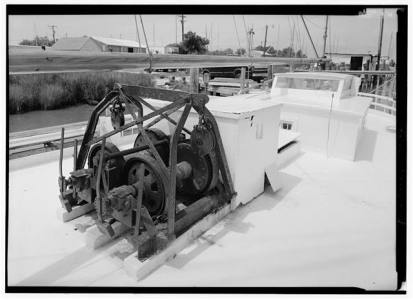
From the Library of Congress --- There may be more photos and possibly drawings on their website.
The 3 pictures below are from The Skipjack by Steve and Patricia Rogers, a book on building a skipjack model.
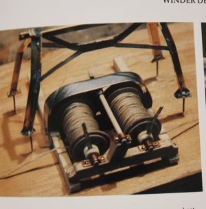
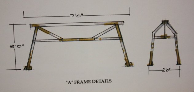
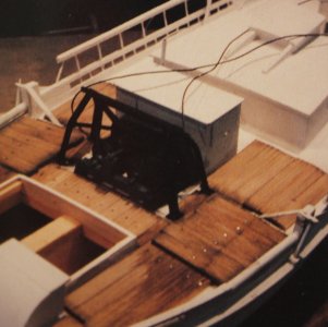
From the Library of Congress --- There may be more photos and possibly drawings on their website.

The 3 pictures below are from The Skipjack by Steve and Patricia Rogers, a book on building a skipjack model.


- Joined
- Jun 29, 2024
- Messages
- 1,365
- Points
- 393

That winder that Allan shows was often powered by an old automobile engine. Inside of the white box.
Roger
Roger
Thanks for everyone's help on my question regarding the windlass. I thought there must have been more than shown on the plans but Roger's explanation of how it would have been hand cranked indicates that was all there was to it.
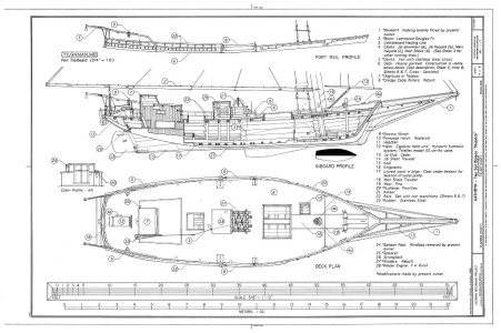
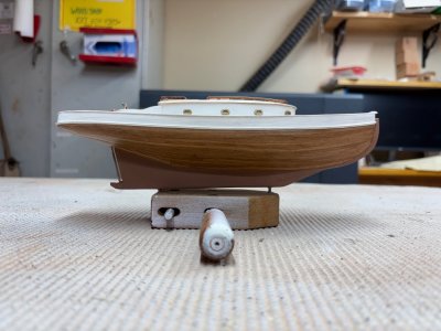
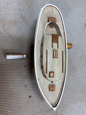
I am actually building a model of the yacht Kathleen (1904) (shown below) that is in the collection of the San Francisco Maritime Park. I just learned they have some photos of her that I hope I can get copies of to answer questions about the deck fittings. If I am sucessful I will post themn here.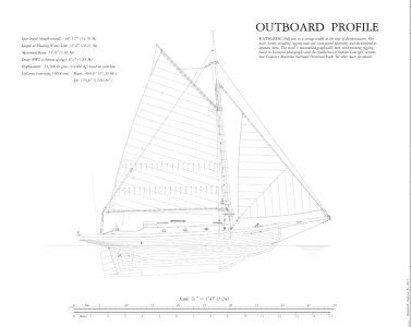
I am actually building a model of the yacht Kathleen (1904) (shown below) that is in the collection of the San Francisco Maritime Park. I just learned they have some photos of her that I hope I can get copies of to answer questions about the deck fittings. If I am sucessful I will post themn here.

- Joined
- Jun 29, 2024
- Messages
- 1,365
- Points
- 393

Looks like an interesting project. Pictures?
Roger
Roger
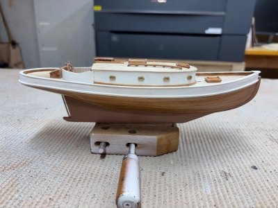
Hull is done, working on deck fittings. I'll take a few pix today.
- Joined
- Jun 29, 2024
- Messages
- 1,365
- Points
- 393

Very nice work and an interesting subject!
Roger
Roger


