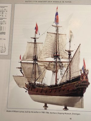
1. Witsen’s Pinas — 1:77 Scratch Build Log
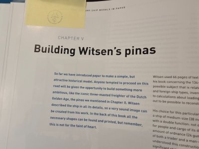
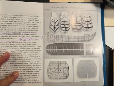
Based on Ab Hoving and Emiel Hoving, "Dutch 17th Century Ship Models in Paper: An Introduction to Scratch Building Paper Ship Models," from SeaWatch Books.
"But remember, this is not for the faint of heart." -- Ab Hoving "17th Century Dutch Ship Models in Paper," pg. 52
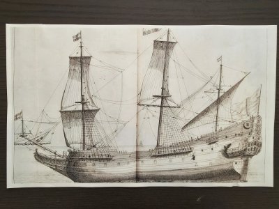
As many know, I am getting towards the end of my 2 Herreshoff Shadow half-hull models, so I am starting my long-awaited build of the second Dutch vessel in Ab Hoving's book. I finished the "Smalschip" several months ago and I have wanted to build Mr. Hoving's "Witsen's Pinas" for some time now. This build is my attempt to construct Witsen’s Pinas at the original 1:77 scale of the Hoving model, using Hoving’s paper-model techniques but incorporating a wooden internal framework (laminated oak sheets). Materials will include paper, cardstock, chipboard, foam, veneer, and aircraft birch plywood.
My plan is to build four 17th Century Dutch hull-only models at 1/48 scale: Witsen's Pinas, the Jaght Heemskerck, the Duyfken and the vlieboot De Zwane and to use those models to find the right vessel from which to build a 1/48 scale model of the Kalmar Nyckel. I know I've annoyed many of you in my crazy quest to build a scale model of Kalmar Nyckel, my local tall ship 20 miles downriver in Wilmington, Delaware.
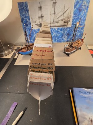
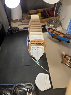
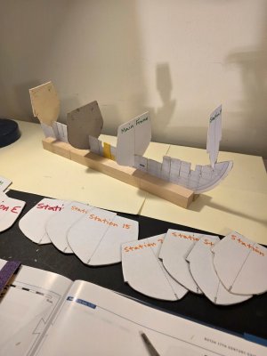
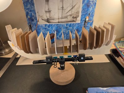
Before beginning the permanent aircraft-plywood structure, I decided to construct a full-size 1:77 wooden maquette of the keel/spine and bulkhead system. The purpose is to test the transfer of Hoving’s paper construction into wood, identify fitting and alignment problems, and gain experience with the hull geometry before cutting the final framework.
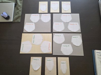
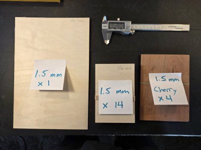
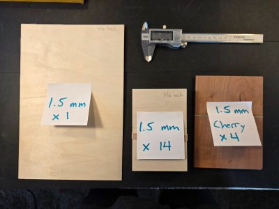
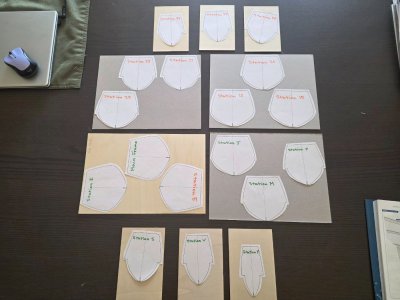
For the maquette I am using oak supplied by a fellow member of my model club: 1/16 × 8 × 11-inch sheets for the principal longitudinal structure and 1/16 × 4 × 6-inch oak cards for the bulkheads.
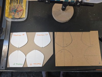
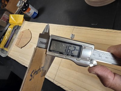
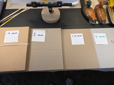
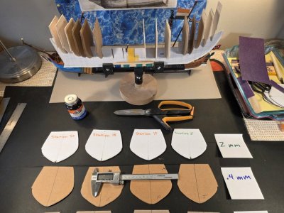
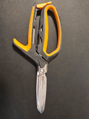
For the formers that did not fit on the oak cards I decided to use laminated cardstock at 1.5 mm (1.1 mm + .4 mm cardstock = 1.5 mm). The laminated bulkheads provide much better support and fair-ability than a single bulkhead because the thicker bulkheads tend to turn into paper mush when cut by the scroll saw. 1.5mm laminated cardstock can be cut precisely with my Fiskar Pro Shears.
Day 1 — Transferring and cutting the spine
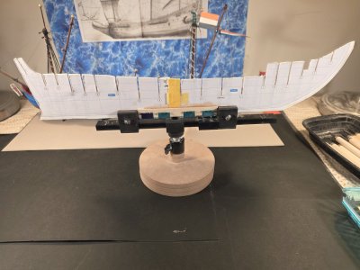
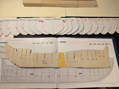
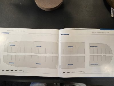
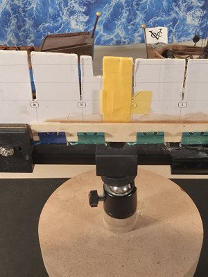
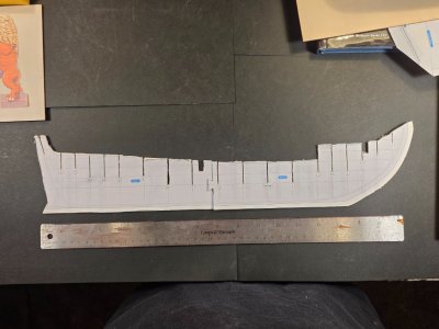
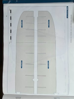
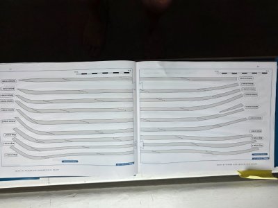
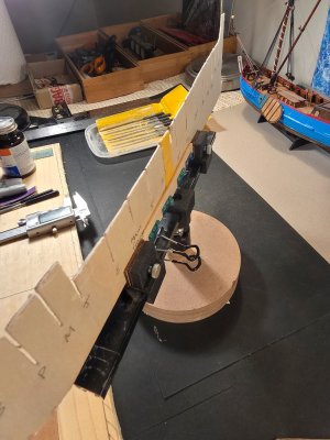
The first task was transferring the 1:77 spine pattern from the Hoving plans to the 1/16" x 8" x 11" oak plywood. The tricky bit is that both 9+ inch sides of the keel (fore and aft) are joined at midships by a tenon joint. The tenon joint made for a weak bond between keel halves, so I added a 3/8" x 1/16" x 5" wooden support for each side supporting the Main Frame and the 6 adjacent bulkheads. Ab Hoving's book recommends doubling or tripling the keel supports, stem and frames at critical support areas.
The pattern was positioned deliberately in relation to the grain direction of the oak, with the long grain running primarily along the longitudinal axis of the hull. This gives the approximately maximum longitudinal strength, particularly through the narrow bow and stern portions.
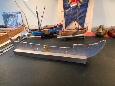
The paper pattern was attached to the oak and the principal outline cut on the scroll saw. The oak proved unexpectedly pleasant to work: it cut easily with little resistance while retaining crisp edges around the narrow bulkhead slots. The stability of the oak plywood for the keel frame with the supports is straight and rigid.
The bulkhead slots were double-cut on the scroll saw, but approximately 3/8 inch of material was deliberately left intact at the bottom of the slots during this first stage. This preserves the strength and alignment of the long spine while the cuts are being made.
The resulting wooden spine is straight and surprisingly rigid. Minor fuzzing and breakout will be left largely untouched for now because this is an experimental structure; final fitting will be determined by the actual oak bulkheads rather than by trying to perfect every slot beforehand. This is bespoke framing for every bulkhead and every joint between the bulkheads and the keel.
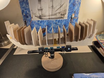
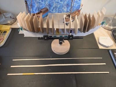
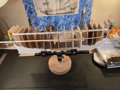
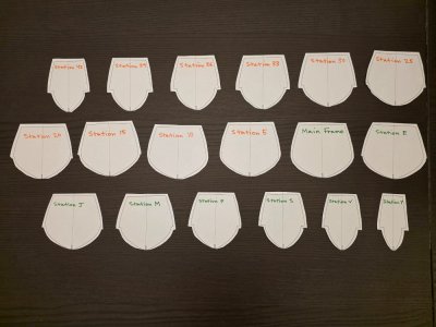
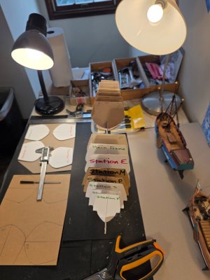
I cut all 18 bulkheads using the oak bulkheads at bow, amidships and at the stern. Then using the laminated 1.5mm papercard where less structure is needed. Each bulkhead has a 5/16" notch at the keel joint/ bottom so I intentionally carved the notch thin. I worked the keel slot with a 1mm mini rasp and the bulkhead notch with a mini chisel and 80 grit sandpaper. Starting thin then widening both openings very gradually is what gives the best fit: no lateral sway from the perpendicular and the keel assembly moves as one piece.
Once again, the exquisitely precise drawings by Ab & Emiel Hoving coupled with the ease of using oak plywood and laminated papercard makes the paper / cardstock method easy - really easy - to get great results!
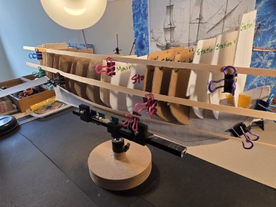
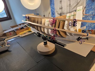
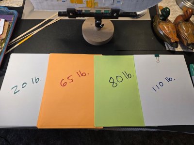
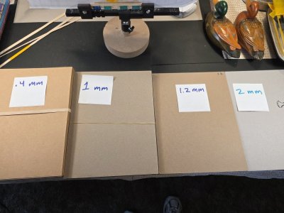
Next: Day 2 — Fairing the bulkheads, using 3 different battens to fair the hull, testing out 3 different thicknesses of cardstock for the 4 decks (.4 mm, 1 mm, and 1.5 mm), and testing out 3 different thicknesses of heavy weighted paper (80 - 50 lb) for the inner-hull planking, followed by testing standard thicknesses of paper (20 - 40 lb) for the pre-scribed hull strakes. Having all the planking laid out one-by-one in the plans blessedly takes the whole planking business out of the equation. Thanks Ab!
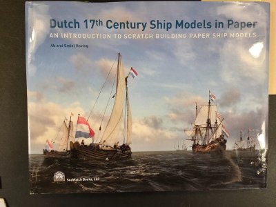
Based on Ab Hoving and Emiel Hoving, "Dutch 17th Century Ship Models in Paper: An Introduction to Scratch Building Paper Ship Models," from SeaWatch Books.
"But remember, this is not for the faint of heart." -- Ab Hoving "17th Century Dutch Ship Models in Paper," pg. 52
As many know, I am getting towards the end of my 2 Herreshoff Shadow half-hull models, so I am starting my long-awaited build of the second Dutch vessel in Ab Hoving's book. I finished the "Smalschip" several months ago and I have wanted to build Mr. Hoving's "Witsen's Pinas" for some time now. This build is my attempt to construct Witsen’s Pinas at the original 1:77 scale of the Hoving model, using Hoving’s paper-model techniques but incorporating a wooden internal framework (laminated oak sheets). Materials will include paper, cardstock, chipboard, foam, veneer, and aircraft birch plywood.
My plan is to build four 17th Century Dutch hull-only models at 1/48 scale: Witsen's Pinas, the Jaght Heemskerck, the Duyfken and the vlieboot De Zwane and to use those models to find the right vessel from which to build a 1/48 scale model of the Kalmar Nyckel. I know I've annoyed many of you in my crazy quest to build a scale model of Kalmar Nyckel, my local tall ship 20 miles downriver in Wilmington, Delaware.
Before beginning the permanent aircraft-plywood structure, I decided to construct a full-size 1:77 wooden maquette of the keel/spine and bulkhead system. The purpose is to test the transfer of Hoving’s paper construction into wood, identify fitting and alignment problems, and gain experience with the hull geometry before cutting the final framework.
For the maquette I am using oak supplied by a fellow member of my model club: 1/16 × 8 × 11-inch sheets for the principal longitudinal structure and 1/16 × 4 × 6-inch oak cards for the bulkheads.
For the formers that did not fit on the oak cards I decided to use laminated cardstock at 1.5 mm (1.1 mm + .4 mm cardstock = 1.5 mm). The laminated bulkheads provide much better support and fair-ability than a single bulkhead because the thicker bulkheads tend to turn into paper mush when cut by the scroll saw. 1.5mm laminated cardstock can be cut precisely with my Fiskar Pro Shears.
Day 1 — Transferring and cutting the spine
The first task was transferring the 1:77 spine pattern from the Hoving plans to the 1/16" x 8" x 11" oak plywood. The tricky bit is that both 9+ inch sides of the keel (fore and aft) are joined at midships by a tenon joint. The tenon joint made for a weak bond between keel halves, so I added a 3/8" x 1/16" x 5" wooden support for each side supporting the Main Frame and the 6 adjacent bulkheads. Ab Hoving's book recommends doubling or tripling the keel supports, stem and frames at critical support areas.
The pattern was positioned deliberately in relation to the grain direction of the oak, with the long grain running primarily along the longitudinal axis of the hull. This gives the approximately maximum longitudinal strength, particularly through the narrow bow and stern portions.
The paper pattern was attached to the oak and the principal outline cut on the scroll saw. The oak proved unexpectedly pleasant to work: it cut easily with little resistance while retaining crisp edges around the narrow bulkhead slots. The stability of the oak plywood for the keel frame with the supports is straight and rigid.
The bulkhead slots were double-cut on the scroll saw, but approximately 3/8 inch of material was deliberately left intact at the bottom of the slots during this first stage. This preserves the strength and alignment of the long spine while the cuts are being made.
The resulting wooden spine is straight and surprisingly rigid. Minor fuzzing and breakout will be left largely untouched for now because this is an experimental structure; final fitting will be determined by the actual oak bulkheads rather than by trying to perfect every slot beforehand. This is bespoke framing for every bulkhead and every joint between the bulkheads and the keel.
I cut all 18 bulkheads using the oak bulkheads at bow, amidships and at the stern. Then using the laminated 1.5mm papercard where less structure is needed. Each bulkhead has a 5/16" notch at the keel joint/ bottom so I intentionally carved the notch thin. I worked the keel slot with a 1mm mini rasp and the bulkhead notch with a mini chisel and 80 grit sandpaper. Starting thin then widening both openings very gradually is what gives the best fit: no lateral sway from the perpendicular and the keel assembly moves as one piece.
Once again, the exquisitely precise drawings by Ab & Emiel Hoving coupled with the ease of using oak plywood and laminated papercard makes the paper / cardstock method easy - really easy - to get great results!
Next: Day 2 — Fairing the bulkheads, using 3 different battens to fair the hull, testing out 3 different thicknesses of cardstock for the 4 decks (.4 mm, 1 mm, and 1.5 mm), and testing out 3 different thicknesses of heavy weighted paper (80 - 50 lb) for the inner-hull planking, followed by testing standard thicknesses of paper (20 - 40 lb) for the pre-scribed hull strakes. Having all the planking laid out one-by-one in the plans blessedly takes the whole planking business out of the equation. Thanks Ab!
Last edited: