• Ships of Scale has incorportated an extra level of security when you log In. Please follow on-screen prompts to acknowledge that you are not a robot via a "Check Box" or a "Pictorial Check Box Puzzle". This is needed due to higher level of AI Activity Security.
  • SUBSCRIBE TO SHIPS IN SCALE TODAY!

    The beloved Ships in Scale Magazine is back and charting a new course for 2026!
    Discover new skills, new techniques, and new inspirations in every issue.

    NOTE THAT OUR NEXT ISSUE WILL BE July/August 2026
  • Win a Free Custom Engraved Brass Coin!!!
    As a way to introduce our brass coins to the community, we will raffle off a free coin during the month of August. Follow link ABOVE for instructions for entering.

"Witsen's Pinas" 1/77 scale scratch build from plans by Ab Hoving

Joined
Dec 26, 2025
Messages
540
Points
268

Location
Bryn Mawr PA US
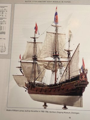
1. Witsen’s Pinas — 1:77 Scratch Build Log
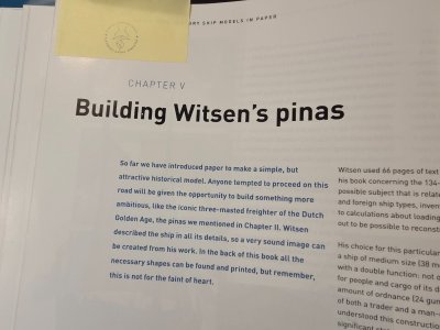
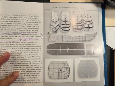
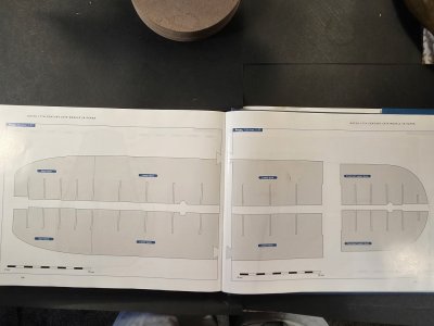
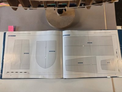
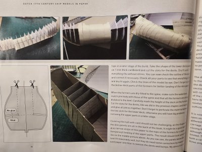
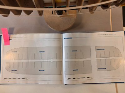
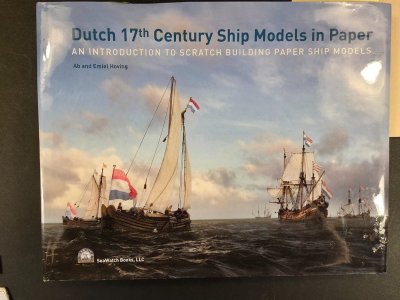
Based on Ab Hoving and Emiel Hoving, "Dutch 17th Century Ship Models in Paper: An Introduction to Scratch Building Paper Ship Models," from SeaWatch Books.

"But remember, this is not for the faint of heart." -- Ab Hoving "17th Century Dutch Ship Models in Paper," pg. 52


As many know, I am getting towards the end of my 2 Herreshoff Shadow half-hull models, so I am starting my long-awaited build of the second Dutch vessel in Ab Hoving's book. I finished the "Smalschip" several months ago and I have wanted to build Mr. Hoving's "Witsen's Pinas" for some time now. This build is my attempt to construct Witsen’s Pinas at the original 1:77 scale of the Hoving model, using Hoving’s paper-model techniques but incorporating a wooden internal framework (laminated oak sheets). Materials will include paper, cardstock, chipboard, foam, veneer, and aircraft birch plywood.

My plan is to build four 17th Century Dutch hull-only models at 1/48 scale: Witsen's Pinas, the Jaght Heemskerck, the Duyfken and the vlieboot De Zwane and to use those models to find the right vessel from which to build a 1/48 scale model of the Kalmar Nyckel. I know I've annoyed many of you in my crazy quest to build a scale model of Kalmar Nyckel, my local tall ship 20 miles downriver in Wilmington, Delaware.

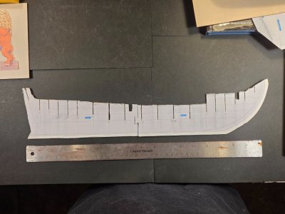
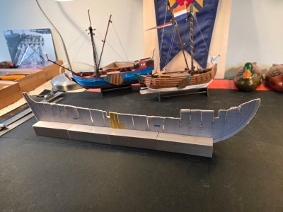
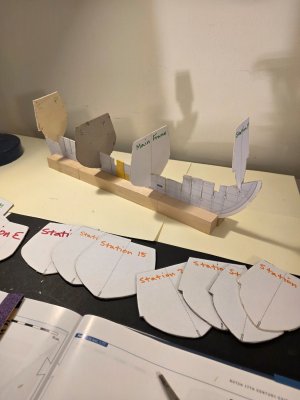
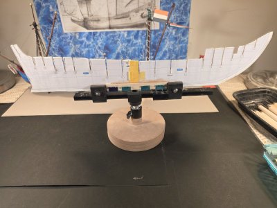
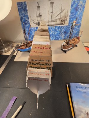
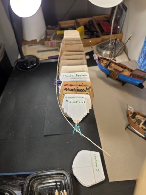
Before beginning the permanent aircraft-plywood structure, I decided to construct a full-size 1:77 wooden maquette of the keel/spine and bulkhead system. The purpose is to test the transfer of Hoving’s paper construction into wood, identify fitting and alignment problems, and gain experience with the hull geometry before cutting the final framework.

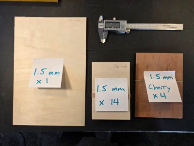
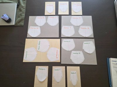
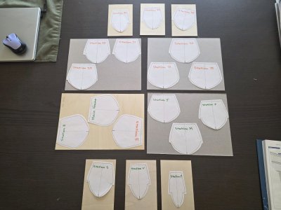
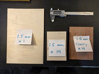
For the maquette I am using oak supplied by a fellow member of my model club: 1/16 × 8 × 11-inch sheets for the principal longitudinal structure and 1/16 × 4 × 6-inch oak cards for the bulkheads.

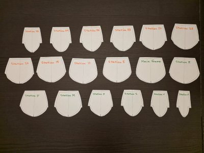
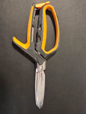
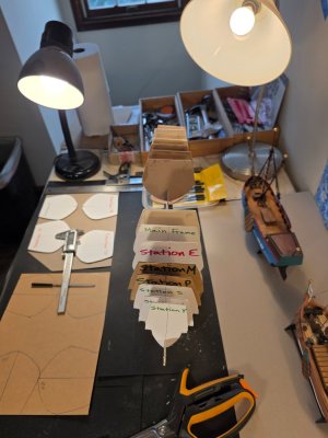
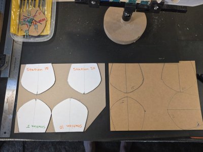
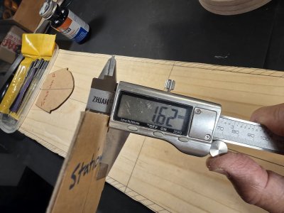
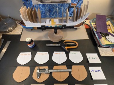
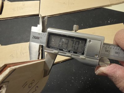
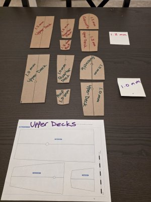
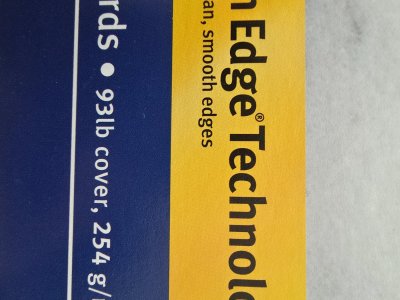
For the formers that did not fit on the oak cards I decided to use laminated cardstock at 1.5 mm (1.1 mm + .4 mm cardstock = 1.5 mm). The laminated bulkheads provide much better support and fair-ability than a single bulkhead because the thicker bulkheads tend to turn into paper mush when cut by the scroll saw. 1.5mm laminated cardstock can be cut precisely with my Fiskar Pro Shears.

Day 1 — Transferring and cutting the spine

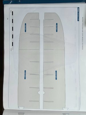
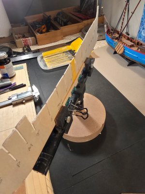
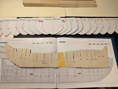
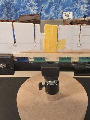
The first task was transferring the 1:77 spine pattern from the Hoving plans to the 1/16" x 8" x 11" oak plywood. The tricky bit is that both 9+ inch sides of the keel (fore and aft) are joined at midships by a tenon joint. The tenon joint made for a weak bond between keel halves, so I added a 3/8" x 1/16" x 5" wooden support for each side supporting the Main Frame and the 6 adjacent bulkheads. Ab Hoving's book recommends doubling or tripling the keel supports, stem and frames at critical support areas.

The pattern was positioned deliberately in relation to the grain direction of the oak, with the long grain running primarily along the longitudinal axis of the hull. This gives the approximately maximum longitudinal strength, particularly through the narrow bow and stern portions.

The paper pattern was attached to the oak and the principal outline cut on the scroll saw. The oak proved unexpectedly pleasant to work: it cut easily with little resistance while retaining crisp edges around the narrow bulkhead slots. The stability of the oak plywood for the keel frame with the supports is straight and rigid.

The bulkhead slots were double-cut on the scroll saw, but approximately 3/8 inch of material was deliberately left intact at the bottom of the slots during this first stage. This preserves the strength and alignment of the long spine while the cuts are being made.

The resulting wooden spine is straight and surprisingly rigid. Minor fuzzing and breakout will be left largely untouched for now because this is an experimental structure; final fitting will be determined by the actual oak bulkheads rather than by trying to perfect every slot beforehand. This is bespoke framing for every bulkhead and every joint between the bulkheads and the keel.

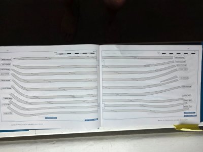
I cut all 18 bulkheads using the oak bulkheads at bow, amidships and at the stern. Then using the laminated 1.5mm papercard where less structure is needed. Each bulkhead has a 5/16" notch at the keel joint/ bottom so I intentionally carved the notch thin. I worked the keel slot with a 1mm mini rasp and the bulkhead notch with a mini chisel and 80 grit sandpaper. Starting thin then widening both openings very gradually is what gives the best fit: no lateral sway from the perpendicular and the keel assembly moves as one piece.

Once again, the exquisitely precise drawings by Ab & Emiel Hoving coupled with the ease of using oak plywood and laminated papercard makes the paper / cardstock method easy - really easy - to get great results!

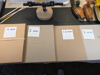
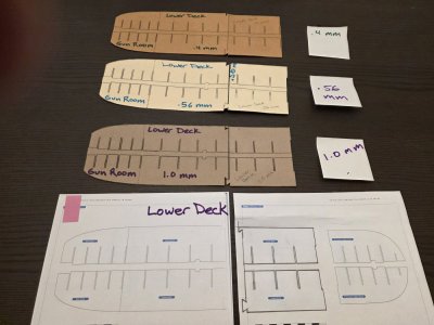
Next: Day 2 — Fairing the bulkheads, using 3 different battens to fair the hull, testing out 3 different thicknesses of cardstock for the 4 decks (.4 mm, 1 mm, and 1.5 mm), and testing out 3 different thicknesses of heavy weighted paper (80 - 50 lb) for the inner-hull planking, followed by testing standard thicknesses of paper (20 - 40 lb) for the pre-scribed hull strakes. Having all the planking laid out one-by-one in the plans blessedly takes the whole planking business out of the equation. Thanks Ab!
20260917_134104.jpg

20260916_221443.jpg

20260916_214404.jpg

20260916_221539.jpg

20260916_221611.jpg

20260916_221950.jpg

20260916_222012.jpg

20260917_095601.jpg

20260917_110705.jpg

20260917_113300.jpg

20260917_124129.jpg

20260917_200143.jpg

20260918_121958.jpg

20260918_144505.jpg

20260918_153544.jpg

20260919_172400.jpg

20260919_192904.jpg

20260918_220741.jpg
 
Last edited:
2. Witsen’s Pinas — 1:77 Scratch Build Log​

Based on Ab Hoving and Emiel Hoving, "Dutch 17th Century Ship Models in Paper: An Introduction to Scratch Building Paper Ship Models," from SeaWatch Books.

"But remember, this is not for the faint of heart." -- Ab Hoving "17th Century Dutch Ship Models in Paper," pg. 52

Build Log Entry #2 — Building the Hull Skeleton​

The first entry ended with the keel frame assembled in the building jig. The next task was to see whether my unconventional material choices would produce a usable hull skeleton.

The answer is: yes — with a few lessons along the way.

Cutting the 18 Frames​

Ab Hoving designed this model primarily for paper and card. For this maquette, I wanted to experiment with a hybrid approach: using wood where useful while retaining some of Hoving's paper-model methods.

1000028760.jpg
I cut the 18 transverse formers from two materials:
  • nine from approximately 1/16-inch oak-faced plywood; and
  • nine initially from 2 mm chipboard/card.
1000028497.jpg
1000029263.jpg
The "oak" was not solid oak sheet, as I had assumed, but thin oak veneer over plywood. That was probably fortunate.

It cut surprisingly well on the scroll saw, remained stiff, and—most importantly—survived repeated fitting into the keel frame's narrow slots.

The 2 mm chipboard was less cooperative.

Under the scroll saw it fuzzed, tore and occasionally turned to mush. Fiskars Pro shears worked considerably better. This confirmed something I had learned while building Hoving's Smalschip: heavy card can make excellent ship-model structure, but the cutting method matters enormously.

The Friction-Fit Experiment​

Rather than cutting every notch to its finished width, I began with narrow cuts, then fitted each former to the keel frame and enlarged the notch as needed.

This proved one of the most useful decisions of the build.

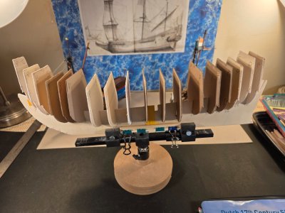
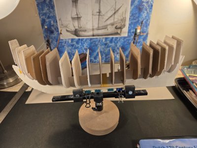
The result was a remarkably firm friction fit. Most frames stand square on the keel without glue. One was slightly loose, but the structure proved far more rigid than expected.

1000029305.jpg
This also showed why I do not want to fair the frames before fitting them.

Each former will be fitted, checked against its neighbors, and faired progressively. That lets the hull indicate where material must be removed instead of requiring me to predict every bevel from the drawings.

1000029310.jpg

The First Complete Dry Fit​


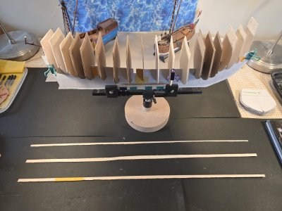
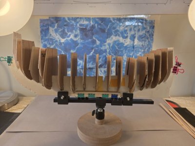
With all 18 stations temporarily installed, Witsen's hull finally emerged from the two-dimensional drawings.

This was the moment I had been waiting for.

1000028769.jpg

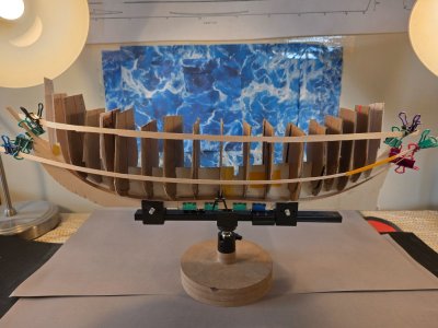
The characteristic Dutch hull is already apparent: a broad midship body, considerable fullness below the waterline, narrowing toward the ends, and the beginnings of tumblehome above.

More importantly, the frames produced a surprisingly fair run from bow and stern. Small adjustments remain, particularly toward the extremities, but nothing suggests that the basic skeleton needs rebuilding.

1000029357.jpg

Batten Day​


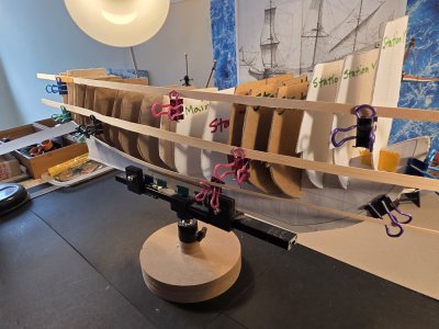
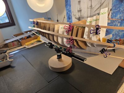
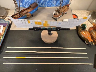
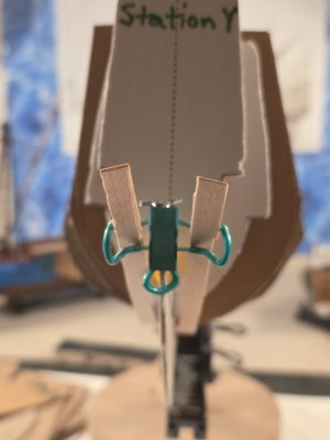
Before committing anything permanently, I ran three temporary battens longitudinally along key hull references:
  1. the upper hull/sheer and deck region;
  2. the turn of the bilge around the main frame; and
  3. the lower hull near the garboard.

This was extremely useful.

1000029360.jpg
A frame can look correct in isolation yet interrupt the hull's longitudinal curve. The battens reveal those errors immediately.

All three runs showed that the basic frame geometry is sound. Some frames will need slight fairing, but I found no abrupt hollow or bump indicating a seriously misplaced or incorrectly shaped former.

The batten test also increased my confidence in the developing tumblehome.

1000029331.jpg

Planning the Skin and Decks​


While assembling the skeleton, I began testing materials for the next stages.

1000029368.jpg

For the under-hull lining, I am trying different paper and card weights rather than committing immediately to the final printed planking.

For the decks, I have been testing approximately 1 mm and 1.4 mm card/chipboard, along with 120 lb cardstock.

1000028466.jpg

Hoving provides camber in the upper decks, which I intend to retain. The lower internal decks are different. Because this is a construction maquette rather than a fully armed model, I will not cut the gunports or reproduce the complete battery of twenty-pounders. The lower decks can therefore remain primarily structural.

1000029390.jpg
The objective of this first Witsen is not a museum-finished model. It is to understand the hull.

Two Rabbets — and an Important Distinction​

Hoving's instructions also revealed a construction detail that initially confused me.

There are effectively two operations associated with plank termination.
1000028942.jpg

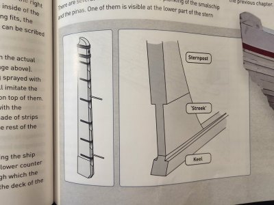
At the keel, stem and sternpost, Hoving adds approximately 0.5 mm to either side of the central spine. This creates shoulders against which the hull covering can terminate—an additive method of producing the rabbet in the paper-model structure.

At the stern, however, Hoving describes the streek, which he translates approximately as the "stern rabbet."

1000029386.jpg

This works in the opposite direction.

Instead of adding material, the stern area is narrowed so the first bottom planks can run cleanly into the aft side of the post. One feature is created by adding thickness; the streek by reducing thickness.

That distinction will matter when the hull is skinned.


What the Maquette Has Already Taught Me​

This experimental hull has already justified building it before attempting the much larger 1/48 version.
1000029365.jpg

The most important lessons so far are:
  • wood-faced plywood works very well for Hoving-style formers;
  • heavy chipboard can work, but prefers shears or a knife to a scroll saw;
  • deliberately undersized slots make excellent friction joints;
  • frames should be fitted and faired progressively rather than shaped completely in isolation;
  • temporary battens are indispensable for checking fairness;
  • the hull should be evaluated as a series of longitudinal curves, not merely as 18 individual cross-sections; and
  • Hoving's apparently simple paper construction contains remarkably sophisticated solutions to traditional wooden shipbuilding problems.
Most importantly, the experiment confirms that Hoving's method can be adapted successfully into a hybrid paper-and-wood construction system.

The next stage will be to refine the fairing, establish the rabbet and streek, finalize the deck material and camber, and prepare the hull for its first covering.

For now, however, I am simply enjoying seeing
Witsen's Pinas finally standing on her frames.

1000029319.jpg
To be continued…

1000029293.jpg

1000028358.jpg

1000029388.jpg

1000029390.jpg
 
Last edited:
3. Witsen’s Pinas — 1:77 Build Log Scratch Build in Paper & Cardstock ​

Based on Ab Hoving and Emiel Hoving, "Dutch 17th Century Ship Models in Paper: An Introduction to Scratch Building Paper Ship Models," from SeaWatch Books.

Build Log Entry #3 — Fairing the Hull: Letting the Battens Decide


This stage of the Witsen pinas has turned into considerably more work than I originally anticipated, but it has also taught me more about the shape of this hull—and about Ab Hoving's approach to modeling Witsen's pinas—than simply assembling the printed parts ever could.

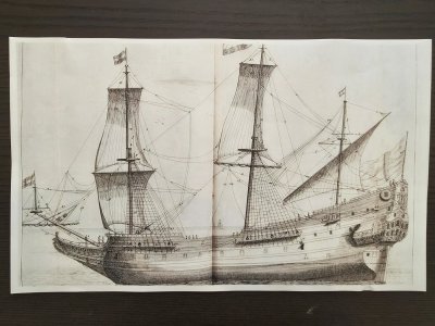
Hoving makes an important observation about Witsen's choice of vessel. The pinas was not merely one particular ship for Witsen to describe. It combined characteristics of merchantman and warship and, in Hoving's words, was “a key to understanding the system of shipbuilding of the era.” (17th Century Dutch Ship Models in Paper, p. 52.)

1000029839.jpg

I am beginning to appreciate that statement at the workbench.

The problem

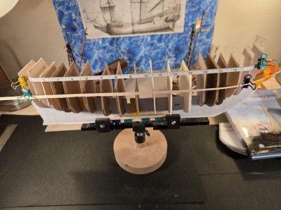
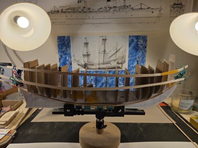
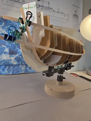
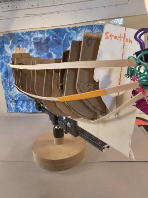
After assembling the keel structure and installing the eighteen bulkheads/formers, I began testing the hull with temporary battens.

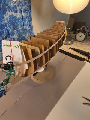
I used three battens on each side:

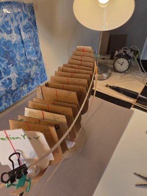
- one approximately following the upper hull/top-wale or sheer region;
- one through the bilge/maximum breadth region; and
- one low on the hull toward the garboard and keel.

1000029744.jpg

The battens immediately revealed something that was much harder to see by looking at individual bulkheads.

1000029826.jpg

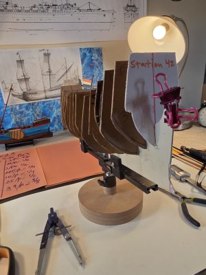
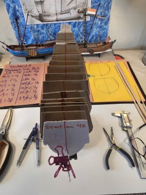
Several formers did not reach the fair curve described by the battens. The discrepancies were not enormous—generally fractions of an inch—but at 1:77 scale they were large enough that simply covering the skeleton would have transferred hollows and irregularities directly into the hull.

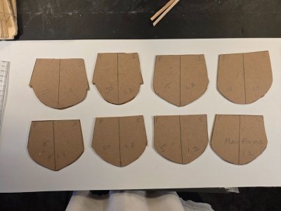
Initially I considered adding small pieces of card to the deficient edges. After measuring the discrepancies station by station, however, I decided that in most cases it would actually be easier and cleaner simply to make new bulkheads.

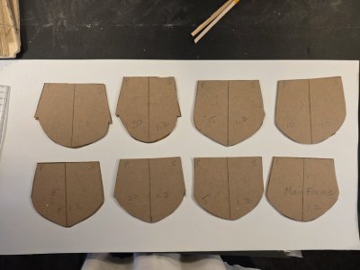
So, without much ado, I remade fourteen of the eighteen bulkheads.

1000029732.jpg

1000029770.jpg

Eighteen bespoke bulkheads

This time I did not treat the printed outline of each former as an absolute boundary.

Each replacement former became, in effect, a bespoke component fitted to its actual position in this particular hull.

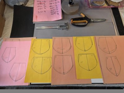
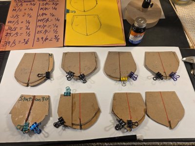
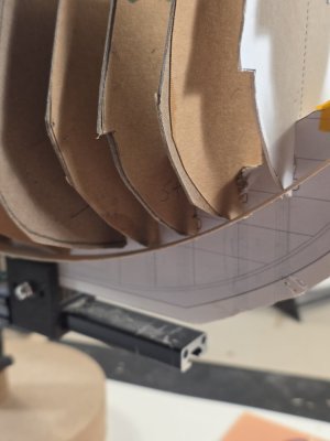
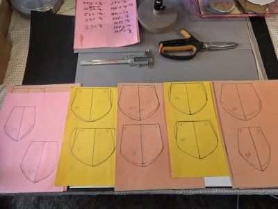
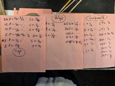
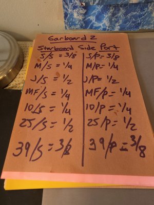
I traced the existing forms onto card, marked the centerlines carefully, recorded the required additions separately on the port and starboard sides, and enlarged the appropriate portions of each former according to what the battens were telling me.

1000029641.jpg

1000029769.jpg

That last point became the governing principle of this stage:

The bulkheads were corrected to the battens—not to the neighboring bulkheads.

1000029729.jpg

A neighboring former might itself be slightly deficient. Copying its relationship would simply propagate the error. A flexible batten spanning many stations gives a much better indication of the continuous surface that the finished hull covering will eventually have to follow.

The photographs of my patterns and handwritten measurements probably explain the process better than I can. This was not elegant drafting. It was repeated measuring, tracing, cutting, fitting, testing, removing, correcting and fitting again.

1000029834.jpg

But it worked.

Three tests instead of one

I also discovered why one fairing batten was not enough.

A former could meet the sheer batten nicely and still fall short at the bilge. Another could agree at the sheer and bilge yet fail to support the hull properly near the garboard.

The three battens therefore became three independent tests of the developing hull form.

After replacing the deficient bulkheads and making several smaller corrections, all eighteen formers now meet the upper and bilge battens, and the battens run continuously across essentially the entire set of stations.

1000029824.jpg

At the garboard I still have three or four localized deficiencies. These are now small, identifiable areas rather than evidence of a larger problem with the frame. I will correct those with small edge laminations rather than remake any more complete bulkheads.

Most importantly, each of the three battens now bears against roughly fourteen to eighteen consecutive bulkheads and describes a smooth longitudinal curve from bow toward stern.

At this point I am calling the basic hull faired.

1000029806.jpg

The keel joints

While all of this was happening I continued checking another potential source of trouble: the relationship between each former and the central keel structure.

All eighteen bulkhead notches now fit snugly into their corresponding keel slots. A few joints that originally had some movement were reinforced until they became firm.

1000029410.jpg

This matters because fairing a former is pointless if the former itself can change position.

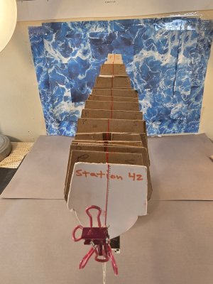
The longitudinal photographs are particularly reassuring here. Despite all the cutting, replacement and adjustment, the bulkheads remain generally perpendicular to the keel and the centerlines remain aligned.

1000029828.jpg

The skeleton may look rather agricultural at this stage, but the curves described by the battens are considerably more orderly than the temporary construction above them might suggest.

Why paper and card are making this possible


There is another passage from Hoving that has stayed with me throughout this exercise. Explaining why he turned to paper modeling, he writes that “Paper modeling can be done at the kitchen table” using relatively simple tools and materials. (17th Century Dutch Ship Models in Paper, p. 7.)

This week has been a rather good demonstration of his point.

Fourteen bulkheads sounded disastrous when I first realized how many needed alteration.

In wood, I suspect I would have spent considerable time debating whether the discrepancy was really serious enough to justify remaking them.

With laminated card the calculation was completely different.

Measure each bulkhead port and starboard against the batten. Trace another pattern. Select the substrate - paper, chip board, foam or wood. Cut it out. Fit it. Put the battens back on. Measure against batten again.

Wrong?

Make another one. Repeat.

The material encourages correction rather than compromise.

1000029533.jpg

The resulting frame is consequently not a pristine assembly of eighteen untouched printed parts. It contains laminations, pencil marks, revised edges and individually altered shapes. But underneath all of that evidence of experimentation, the three battens now describe something that was not nearly as convincing before:

a continuous hull.

That seems much more important.

1000029768.jpg

Where I am leaving the Witsen


This is a convenient stopping point.

I am going to leave the pinas on the building stand for several days while I return to my two Herreshoff Shadow half-hulls.

When I come back to Witsen, the nature of the project changes again.

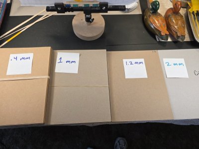
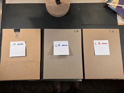
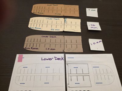
The next major work will be concerned with the interior geometry of the hull: establishing the lower and upper decks, cutting or removing the appropriate portions of the temporary bulkheads, introducing the deck supports, and preserving the proper cambers fore and aft (saddleback) and athwartships - the cambereed deck extends to the poop deck, main deck, quarter deck and forecastle. We will use either 1mm chip board or 1.2mm chip board whichever can hold the camber.

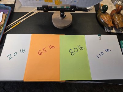
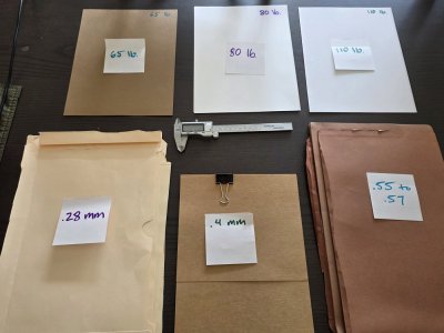
We will be using 110 lb paper stock for the lower decks because it is not structural and it won't be seen below the top decks.

1000029833.jpg

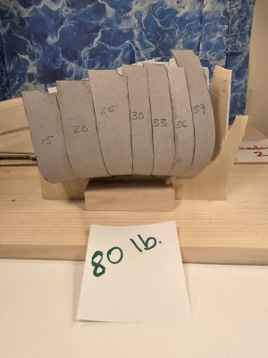
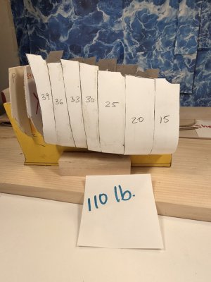
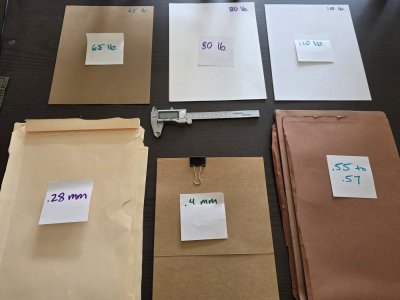
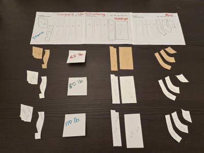
At the same time I will begin testing the material for the first under-hull covering. The present candidates are 80 lb and 110 lb paper stock. The covering needs enough strength to unite the eighteen formers into a continuous shell while remaining flexible enough to accept the considerable curvature of this Dutch hull without imposing its own shape upon it.

And, of course, we must preserve the substantial TUMBLEHOME built into the Witsen's upper wales.

There will also be additional support at the bow and stern, where the hull covering must make the difficult transition from the final formers into the stem and stern structure. Thinking about balsa or basswood supports at the bow and stern to ensure that the planks bend correctly at each end.

1000029381.jpg

But those are problems for the next stage.

For now, after considerably more cutting and fitting than expected, I finally have eighteen firmly seated bulkheads and three fairing battens telling essentially the same story.

For the first time, I think I can stop looking at the individual formers and begin to see Witsen's pinas emerging from them.

1000029839.jpg

1000029829.jpg

1000029805.jpg

20260929_123939.jpg

20260929_121326.jpg

20260927_172627.jpg

1000029556.jpg

1000029798.jpg
 
Last edited:
Looks like the hull is coming along! Fairing a paper hull sounds very challenging as you can't really sand it in the same way as wood.

It may be the angle or other oddities of photography, but you may want to double check that the bulkheads are symmetrical. In photos like the third from the last, some look a bit off, which may explain some of the batten issues.
 
Looks like the hull is coming along! Fairing a paper hull sounds very challenging as you can't really sand it in the same way as wood.

It may be the angle or other oddities of photography, but you may want to double check that the bulkheads are symmetrical. In photos like the third from the last, some look a bit off, which may explain some of the batten issues.
JC - The bulkheads are very rough at this point. I will need to install the lower and upper decks, the deck supports, and the first hull planking before the bulkheads get trimmed down to the top decks. I also have to fair each bulkhead to preserve the tumblehome, so the decks will be pretty sketchy until I get to the second planking in a couple of weeks. Thanks for watching ...it's a fun build.
 
Sorry @Ignatius27 but I feel obliged to make two corrective remarks.
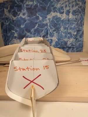
1. You will have to cut a recess in the underside of your stations, so that the frame lands at the keel. See the drawn frames in the book.
2. In my opinion you confused the front and the back of the frames. The high narrow ones should be at the aft part , the low wide ones at the front. The front has the round shape, the aft part is almost straight up.
I hope this helps to get the shape that you actually want.
Ab
 
Sorry @Ignatius27 but I feel obliged to make two corrective remarks.
1. You will have to cut a recess in the underside of your stations, so that the frame lands at the keel. See the drawn frames in the book.
2. In my opinion you confused the front and the back of the frames. The high narrow ones should be at the aft part , the low wide ones at the front. The front has the round shape, the aft part is almost straight up.
I hope this helps to get the shape that you actually want.
Ab
Thanks Ab for your observations. I'm glad I can catch it and fix it before we have to glue the bulkheads to the keel. I'll post pictures of the fix. As the creator of this ship and these plans, I invite you to share your perspectives, observations or corrections on my approach. They are much appreciated.
Ignatius
 

3b. Witsen’s Pinas — 1:77 Scratch Build Log​

Based on Ab Hoving and Emiel Hoving, "Dutch 17th Century Ship Models in Paper: An Introduction to Scratch Building Paper Ship Models," from SeaWatch Books.

Material testing day. One of the best things about building in paper and cardstock is the flexibility that the builder gets in choosing materials for their models. You are not limited to the materials supplied by the manufacturer, you never have any missing parts, and one gets to be as creative as possible.

So I spent much of the day testing out different materials for 1. Underhull covering. 2. Upper decks - poop, quarter, main and forecastle decks. 3. Lower decks and gun rooms, and other sundry parts that will be worked soon.

I spent alot of time today doing major surgery on the keel and bulkheads without much more progress to report.

1000029988.jpg


1000029987.jpg

1000029982.jpg

1000029515.jpg
1000029555.jpg

1000029534.jpg

1000029560.jpg

20260923_205136.jpg

7cc6a8e1-bc4d-4391-ba3c-0b44fad69879-1_all_30874.jpg

20260929_131437.jpg

1000029557.jpg
 
Last edited:
Back
Top