- Joined
- May 1, 2023
- Messages
- 115
- Points
- 113

Hi everyone!
I'd like to begin with a question: How do you create wooden blocks?
This question has become quite significant for me, and I'm actively seeking an optimal solution.
So, any of your ideas, experiences, or links would be greatly appreciated!
In most cases, the question "how to make blocks" doesn't arise. Generally, you either possess a quality kit containing the appropriate blocks, or you don't concern yourself with it, opting for a quicker route where the block quality matches the overall kit quality.
At least, that was my situation. I never attempted to craft blocks until I embarked on my "Santa Maria Project." After using high-quality kits with impeccably crafted blocks, I find it hard to accept what Amati offers in the Santa Maria kit. Given that I'm now approaching the rigging stage in my project, I've initiated experiments in block-making.
I believe utilizing a good laser would make the process somewhat easier, but unfortunately, I don't have access to one. While printing the blocks is feasible, I desire them to be wooden. Regrettably, available printers cannot handle wood printing... yet.
Consequently, my only viable option is CNC machining.
I've established several prerequisites:
1. The technology must be scalable and easily replicable, as I might require dozens of blocks.
2. It should be relatively simple, minimizing preparation and manufacturing time.
3. I need the capability to create both single-sheave and multi-sheave blocks.
4. The finished simulated blocks should closely resemble real ones, even in 1:64 or 1:72 scale.
I've conceptualized two machining approaches:
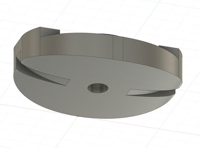
The first theoretically promises superior results but necessitates double-sided machining, which I'm trying to avoid due to the higher precision demands on stock and fixtures.
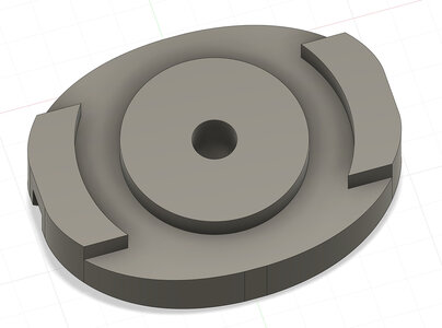
The second approach is simpler, involving only one-sided processing, but it's suitable only for one- or two-sheaved blocks.
Today, I decided to explore the simpler approach and present the initial outcome.
The process involves four fundamental stages:
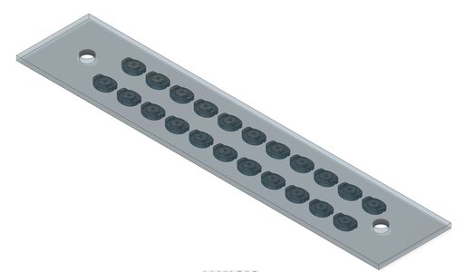
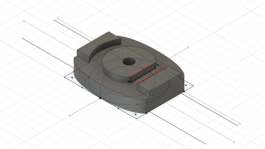
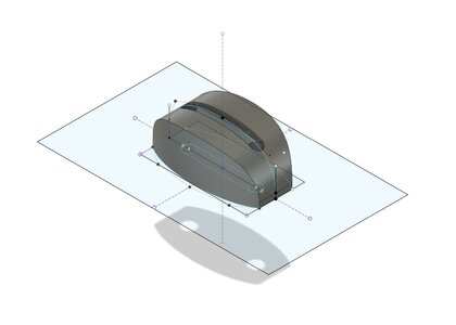
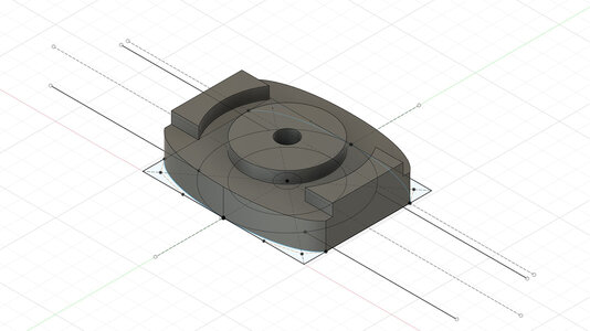
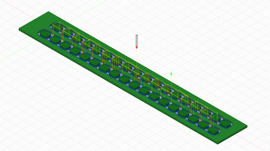
1. Modeling: I utilized Fusion 360, as usual. The modeling process is relatively quick. Most of my time was spent experimenting with various cutting strategies to achieve optimal results with minimal production time.
2. Wooden stock preparation: The final block is 2.3 mm thick, so the stock must precisely match this thickness. I opted for pear wood, and the bar needed to be precisely 1.15 mm thick. CNC machining enables such precision for wooden details.
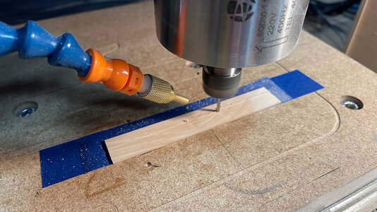
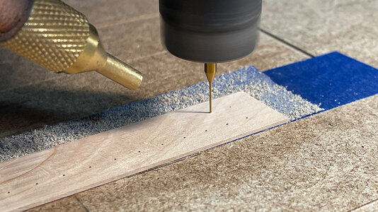
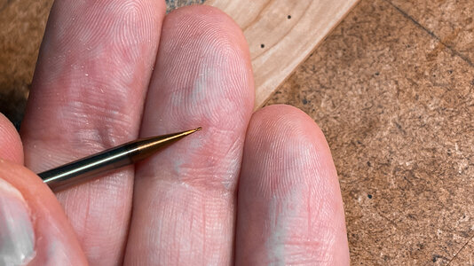
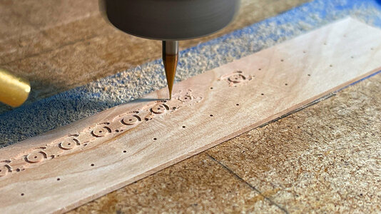
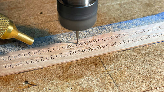
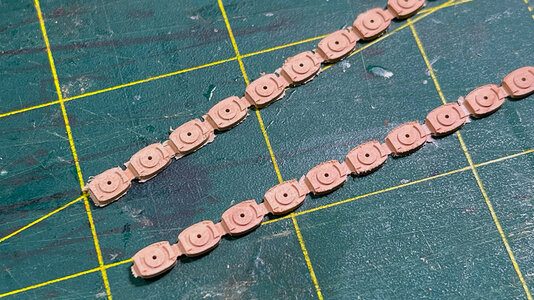
3. Detail cutting: I employed a 0.6 mm drill for hole-making and a 0.4 mm endmill for internal details like the sheave. The contour of the details was carved using a 1 mm mill. Given the miniature size of the tools, the main challenge was avoiding breakage.
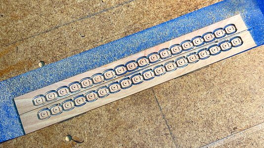
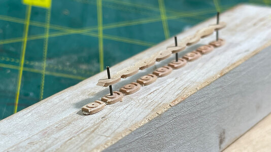
4. Assembly and finishing: This stage proved straightforward. I had to accurately join the two halves of the blocks together. I accomplished this while the blocks were still connected in a "chain," not yet separated.
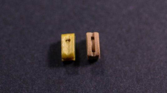
This marks the initial result compared to what the kit provides. The primary goal was to assess the viability of the approach, and it seems to be satisfactory. Now, I'll focus on refining the design and process details.
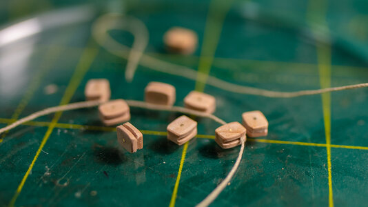
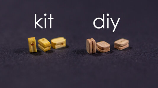
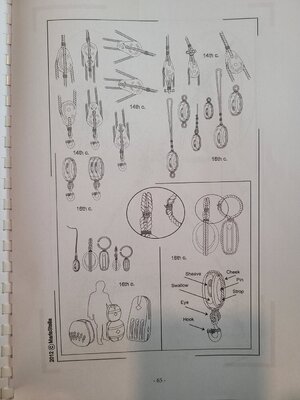
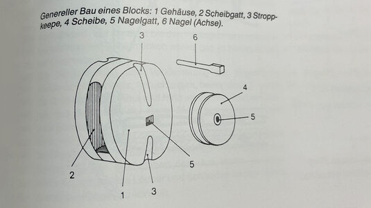
The current block design isn't perfect; they currently resemble rectangles but should have a more "lentil-like" shape. Another challenge I haven't addressed yet is the channel for the rope on the top and sides of the block (#3 in the picture). While it's possible to manually create this channel with a needle file, it's a time-consuming and imprecise method. If you have any ideas, please share them.
I intend to continue these experiments and will keep sharing my progress here.
I'd like to begin with a question: How do you create wooden blocks?
This question has become quite significant for me, and I'm actively seeking an optimal solution.
So, any of your ideas, experiences, or links would be greatly appreciated!
In most cases, the question "how to make blocks" doesn't arise. Generally, you either possess a quality kit containing the appropriate blocks, or you don't concern yourself with it, opting for a quicker route where the block quality matches the overall kit quality.
At least, that was my situation. I never attempted to craft blocks until I embarked on my "Santa Maria Project." After using high-quality kits with impeccably crafted blocks, I find it hard to accept what Amati offers in the Santa Maria kit. Given that I'm now approaching the rigging stage in my project, I've initiated experiments in block-making.
I believe utilizing a good laser would make the process somewhat easier, but unfortunately, I don't have access to one. While printing the blocks is feasible, I desire them to be wooden. Regrettably, available printers cannot handle wood printing... yet.
Consequently, my only viable option is CNC machining.
I've established several prerequisites:
1. The technology must be scalable and easily replicable, as I might require dozens of blocks.
2. It should be relatively simple, minimizing preparation and manufacturing time.
3. I need the capability to create both single-sheave and multi-sheave blocks.
4. The finished simulated blocks should closely resemble real ones, even in 1:64 or 1:72 scale.
I've conceptualized two machining approaches:
The first theoretically promises superior results but necessitates double-sided machining, which I'm trying to avoid due to the higher precision demands on stock and fixtures.
The second approach is simpler, involving only one-sided processing, but it's suitable only for one- or two-sheaved blocks.
Today, I decided to explore the simpler approach and present the initial outcome.
The process involves four fundamental stages:
1. Modeling: I utilized Fusion 360, as usual. The modeling process is relatively quick. Most of my time was spent experimenting with various cutting strategies to achieve optimal results with minimal production time.


2. Wooden stock preparation: The final block is 2.3 mm thick, so the stock must precisely match this thickness. I opted for pear wood, and the bar needed to be precisely 1.15 mm thick. CNC machining enables such precision for wooden details.

3. Detail cutting: I employed a 0.6 mm drill for hole-making and a 0.4 mm endmill for internal details like the sheave. The contour of the details was carved using a 1 mm mill. Given the miniature size of the tools, the main challenge was avoiding breakage.


4. Assembly and finishing: This stage proved straightforward. I had to accurately join the two halves of the blocks together. I accomplished this while the blocks were still connected in a "chain," not yet separated.


This marks the initial result compared to what the kit provides. The primary goal was to assess the viability of the approach, and it seems to be satisfactory. Now, I'll focus on refining the design and process details.


The current block design isn't perfect; they currently resemble rectangles but should have a more "lentil-like" shape. Another challenge I haven't addressed yet is the channel for the rope on the top and sides of the block (#3 in the picture). While it's possible to manually create this channel with a needle file, it's a time-consuming and imprecise method. If you have any ideas, please share them.

I intend to continue these experiments and will keep sharing my progress here.
Last edited:


