YQ Bluenose Ted R

From your pictures I deduced that the fwd mast step was approximately in the right spot, give or take a few millimeters.
Having said that, when in doubt, don’t tear it apart, but check, measure, check and when found not conforming, first prepare a plan of action. Better yet, put it aside for a day or two.
 
Plus a quick conversation with the drawings could be very enlightening…
I went over the drawings. I got confused over the first deck beam location. I now think I installed it correctly. I think I installed the opening for the foremast one beam aft on the upper deck. All I have to do is move that three beam section one frame forward. That's also where the deck beams started seeing to being too short. I wasn't sure if I had sanded the ends of the beams too much.
I have learned that with this kit if it doesn't fit perfectly the alarm bells should start going off and so e checking is needed .
This kit is marked as being suitable for the advanced beginner. This I wholeheartedly disagree with: it may be true for the spars and the standing and running rigging, but the hull is a totally different animal.
The hull is complex and any error will wiggle its way into the final result. One does need to be able to read drawings and read and understand the instructions, plus having the ability, as mentioned by Dan, to read and plan at least two steps ahead.
And that's just sticking to the plan. Needless to say that going into extensive customizations, this will raise the complexity considerably. I think I never checked and re-checked everything as much as I did for this build, plus, when in doubt, I consulted the veterans on this site.
If one would really want to go for a beginners kit, I think the old Billing Boats Bluenose kit in 1:65 is a good choice, despite all it's misgivings. The other kits, from Artesania Latina, Amati, Model Shipways, I am not familiar with, so no opinion from me on those kits.
 
Hi Ted. I am back from my holiday and read your confusion about the beam locations. In addition to what Daniel and Johan have already written, first start checking in 3 steps:
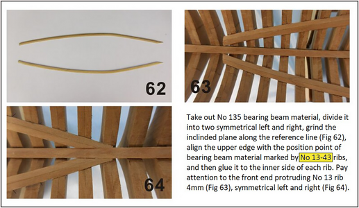
1: the position of the lower deck beams on the lower bearing beams 135. That is your base alignment! Like what is written in the (translated) manual pag. 11:
1717253888451.png
I high-lighted the numbers of the lower bearing beams over the frames 13 till 43.
Then you can see on the plan 8-1, fig. 9 what the position is of the lower deck beams 75-76, 77-90 and 91-101. They are placed in front of the frames. Beam 75 is in front of frame 13, 76 in front of 14, etc etc.
For an extra check: beam 91 is in front of the frame 31 with the 2 holes for the pumps.
If that is correct:
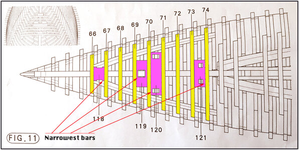
2: In the bow, the middle deck beams 66 till 74 are positioned in front of the frames 4 till 12 and are on the middle bearing beams 136. See plan 8-1, fig 11 and pag. 14-1 of the translated manual.
214a Beams.jpg
In this picture I also highlighted the position of the 4 blocks between the middle deck beams.
If that is also correct:
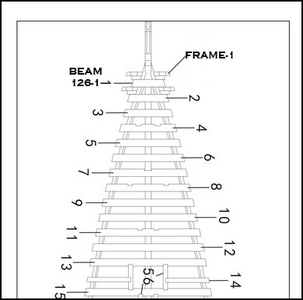
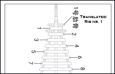
3: The upper deck beams are placed on the upper bearing beams behind =in front and against the frames: 126-1 is behind frames 1 = in front and against 2, 126-2 is behind frame 2 = in front and against 3, etc etc. (See posts #536 + #537)
This drawing is from pag 15 of the manual where I named frame 1 and beam 126-1:
1717256794133.png

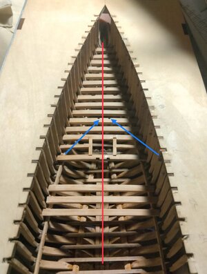
If those beams on the 3 decks are all in the correct position, then both mast-steps and the openings for the masts between de deck beams would be in line.
Hopefully this will help you further.
Regards, Peter
 
Last edited:
I found a huge mistake made earlier. When placing the lower deck beams I started one frame aft of the correct position by not understanding how the glued multi part at the bow cut off point height worked with these lower beams. This resulted in the foremast step being one frame aft of its correct position. I was not able to detect this error until testing how the mast fitted through the finish deck part. Now have to remove the upper deck beams. Cutoff the glued bow parts to correct height. Remove the lower deck beams and move them all forward one frame.
I was really in well over my head when I started this project but didn't realize how much. Despite a second major setback I'm feeling more confident and feel my abilities have grown immensely. (Maybe that's hopeful thinking.). At any rate the use of water soluble glue in most locations is helpful.
I have been getting a hint that things weren't quite right for about the last ten upper deck beams but thought the sawing and chopping I had to do to remove all the frames from the keel has resulted in the slight misalignment I was seeing.
I am a little disheartened and little sadder bit wiser.
If not for the excellent work I've seen on this site i might be tempted to find a work around solution but believe it is the catching and correcting of these major blunders that are the tuition that lead to the results I want.
Humbly,
TedView attachment 450676View attachment 450677View attachment 450679
Ted,

You might check the deck beam with the cut-outs for the bits; they appto be off center. (Might be the picture...)


IMG_0493.jpeg
 
Hi Ted. I am back from my holiday and read your confusion about the beam locations. In addition to what Daniel and Johan have already written, first start checking in 3 steps:
1: the position of the lower deck beams on the lower bearing beams 135. That is your base alignment! Like what is written in the (translated) manual pag. 11:
View attachment 450718
I high-lighted the numbers of the lower bearing beams over the frames 13 till 43.
Then you can see on the plan 8-1, fig. 9 what the position is of the lower deck beams 75-76, 77-90 and 91-101. They are placed in front of the frames. Beam 75 is in front of frame 13, 76 in front of 14, etc etc.
For an extra check: beam 91 is in front of the frame 31 with the 2 holes for the pumps.
If that is correct:
2: In the bow, the middle deck beams 66 till 74 are positioned in front of the frames 4 till 12 and are on the middle bearing beams 136. See plan 8-1, fig 11 and pag. 14-1 of the translated manual.
View attachment 450755
In this picture I also highlighted the position of the 4 blocks between the middle deck beams.
If that is also correct:
3: The upper deck beams are placed on the upper bearing beams behind the frames: 126-1 is behind frames 1, 126-2 is behind frame 2, etc etc.
This drawing is from pag 15 of the manual where I named frame 1 and beam 126-1:
View attachment 450759

If those beams on the 3 decks are all in the correct position, then both mast-steps and the openings for the masts between de deck beams would be in line.
Hopefully this will help you further.
Regards, Peter
Thank you for all the help. I'll start checking from the top
 
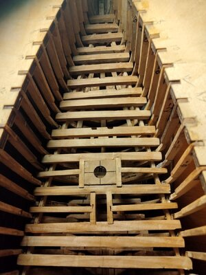
I remove the previously installed upper deck beams and have started reinstalling them on the correct side. Have installed back to frame 12. Checked fitment of the Samson post through the finished deck, beams and down to the lower deck.
 
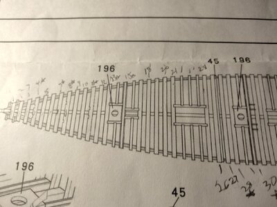
Should, Parts 196, figure 12, sheet 8-1; be enlarged to fit the masts prior to glueing to the deck beams?
Thanks,
Ted
17176199199443716985034111843762.jpg
 
Despite all my efforts I was not able to get beams 4 and 11 to align with the holes in the finished deck. Rather than having no reinforcement for the finish deck at these locations I moved the beams slightly aft to get perfect alignment. I don't find a problem with this since these locations are not visible on the finished model.
To the purists who might read this I apologize but have accepted the limits of my abilities and have moved on to continue the model. I have not changed my goal of perfection for future steps
I have just installed beam 30.17176330531623430428886038422670.jpg
 
Despite all my efforts I was not able to get beams 4 and 11 to align with the holes in the finished deck. Rather than having no reinforcement for the finish deck at these locations I moved the beams slightly aft to get perfect alignment. I don't find a problem with this since these locations are not visible on the finished model.
To the purists who might read this I apologize but have accepted the limits of my abilities and have moved on to continue the model. I have not changed my goal of perfection for future steps
I have just installed beam 30.View attachment 451580
My guess is that the frames are not really at a constant pitch, causing the spars not being parallel to one another.
Readjusting the beams could be the better option.
 
My guess is that the frames are not really at a constant pitch, causing the spars not being parallel to one another.
Readjusting the beams could be the better option.
You are correct. Removing all the frames did some damage to the jig fixture. That along with inept sanding to remove the char has caused the waviness.
I'll go through and see if I can correct it.
Thanks for the input.
 
Hopefully your prefab deck openings will coincide with your crossbeam openings. If they do not, then you will have a major redo on your hands. All of your upper deck cross beams should have been bonded to the fore side of the ribs then come in with the short pcs 56,57-60 etc. and trim them to fit in their respective notches.
 
I just read the post from Daniel and got triggered on his quote:
All of your upper deck cross beams should have been bonded to the fore side of the ribs
That's contrary to what I wrote:
3: The upper deck beams are placed on the upper bearing beams behind the frames

I can't refer to my own build because I made a completely different setup of the deck beams.
So, I made a closer look to the manual and drawings. There is reason for some confusion.
Why do they point rib/frame 1 and beam 126-1 close to each other, draw rib/frame 2 and pointed then the number '2' behind that second frame ???
1717674863917.png
The beam is drawn 'clamped' between rib/frame 1 and 2, but the beams are not that wide.

In the Manual they wrote (translated): " .....Note the back close to the ribs ......"
I suppose they mean "..... Note the back (of the beams) close to the ribs ........"
Then beam 1 must be in front and against to rib/frame 2 etc.
Why do you draw with (Chinese) text special attention to rib 1 on that drawing?
That's why I interpreted it as "the beams behind of the frames".

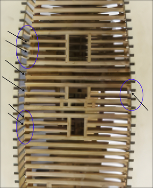
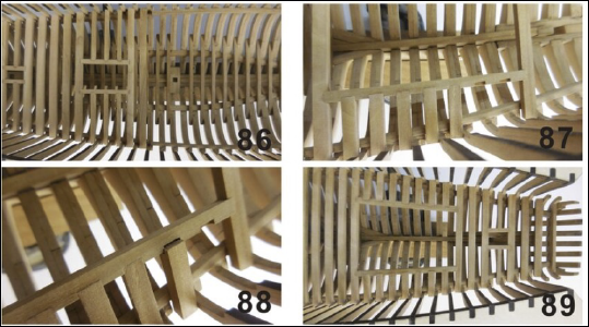
I made a closer look to the picture 85 on page 15. The picture has a low resolution. So I pimped it a bit up.
Then you can see that the lay the beams in front and against the ribs/frames. It's hard to see because they made the picture with a wide angle:
1717675984413.png
The black arrows are pointing to where you can see the beams in front of the ribs/frames and the gaps in front of the beams.
On the next page of the manual there are some better pictures, but still in a low resolution:
1717677261953.png

So, Ted: Sorry for my misinformation and Daniel is right!
Perhaps you can get now a better alignment for the vertical beams in the front.
Regards, Peter
 
Last edited:
I just read the post from Daniel and got triggered on his quote:

That's contrary to what I wrote:


I can't refer to my own build because I made a completely different setup of the deck beams.
So, I made a closer look to the manual and drawings. There is reason for some confusion.
Why do they point rib/frame 1 and beam 126-1 close to each other, draw rib/frame 2 and pointed then the number '2' behind that second frame ???
View attachment 451599
The beam is drawn 'clamped' between rib/frame 1 and 2, but the beams are not that wide.

In the Manual they wrote (translated): " .....Note the back close to the ribs ......"
I suppose they mean "..... Note the back (of the beams) close to the ribs ........"
Then beam 1 must be in front and against to rib/frame 2 etc.
Why do you draw with (Chinese) text special attention to rib 1 on that drawing?
That's why I interpreted it as "the beams behind of the frames".

I made a closer look to the picture 85 on page 15. The picture has a low resolution. So I pimped it a bit up.
Then you can see that the lay the beams in front and against the ribs/frames. It's hard to see because they made the picture with a wide angle:
View attachment 451605
The black arrows are pointing to where you can see the beams in front of the ribs/frames and the gaps in front of the beams.
On the next page of the manual there are some better pictures, but still in a low resolution:
View attachment 451606

So, Ted: Sorry for my misinformation and Daniel is right!
Perhaps you can get now a better alignment for the vertical beams in the front.
Regards,
 
Oh my, That's disheartening. I removed all the deck beams and reinstalled them behind the frames.
Hopefully your prefab deck openings will coincide with your crossbeam openings. If they do not, then you will have a major redo on your hands. All of your upper deck cross beams should have been bonded to the fore side of the ribs then come in with the short pcs 56,57-60 etc. and trim them to fit in their respective notches.
My deck openings are ok. As I said earlier I fudged the beams for the Samson post and I think. Chain lockers to make them fit perfectly.
 
Oh my, That's disheartening. I removed all the deck beams and reinstalled them behind the frames.

My deck openings are ok. As I said earlier I fudged the beams for the Samson post and I think. Chain lockers to make them fit perfectly.
My apologies again, Ted. But as the deck openings are now ok, make a final check with the deck sheets. If you use them.
Regards, Peter
 
Back
Top