Le Coureur 1776 CAF Model by OT1138

Joined
Sep 22, 2020
Messages
239
Points
203

Hi everyone,

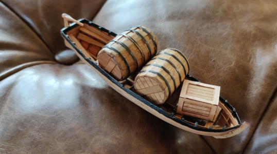
I received my CAF model recently and like others, was missing E1/E2. Seeing as I had to wait for these to arrive as well as the Ancre monograph, I thought I would start with the smaller boat, some barrels and creates from the associated kits. At the very least, I hoped to get a little bit of familiarity with the CAF pieces.

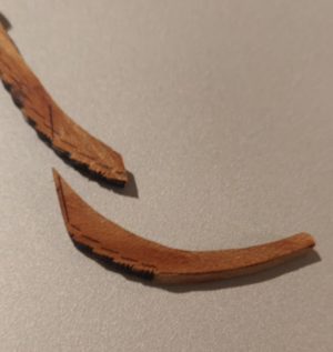
First impressions - the frames for the boat are very fragile! #2 broke in half while sanding. I thought that the jig would help to reposition this properly but it ended up going down too low on the keel. No way to tell this while it's in the jig.
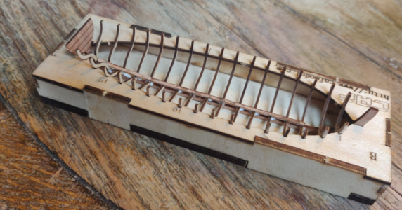
1602373204958.png

The tolerances are very tight. While trying to pop the completed frame out of the jig, two of the frames broke. Lesson for other builders - use some snips and carefully cut the jig away in pieces.
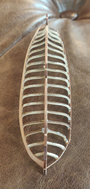
1602373395297.png

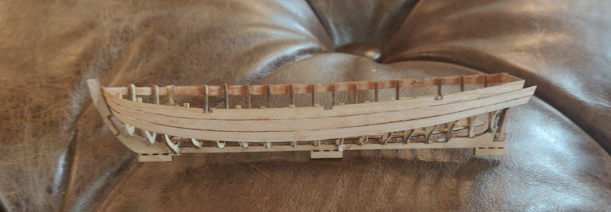
Another problem is that the instructions are really quite minimal. There's no indication of where to play the top plank on the frames. I didn't have the Ancre monograph either at this point so I just guessed. I got lucky and it ended up pretty close, but I ended up with a small (.5mm) gap between the keel and the garboard strake.

Another tip - I would gently sand the char off the frames prior to assembly. It's just too difficult once things have been glued in place.
1602373547930.png

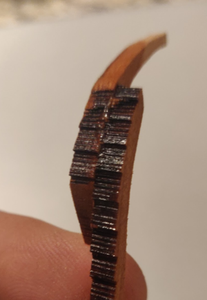
The planks come pre-splined, which is pretty awesome. However... there are microdots on the edges which are nearly impossible to sand down due to the fragility of the planks. This wasn't evident to me until I had gotten a few done. I did my best but ended up with these tiny dots which could be seen when the boat is held up in front of a light.

Nevertheless, I was really pleased with the fact that there were almost no clinkers or gaps on the planks. Well done.
1602373708993.png

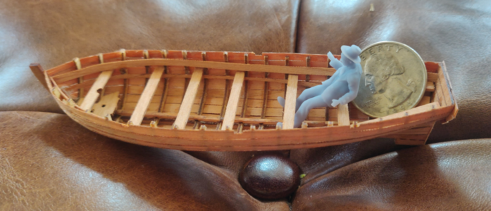
You can actually see some of the microdots between the planks on the lower right of the photo above. You can also see that I didn't sand the chaf off on the inside of the frames... wish I had done that now. You guys will at least know better. It didn't look too bad though and perhaps it will even look desirable at the end.
 
Last edited:
From that last photo, you'll also note that the top inner plank running horizontally is a little low. The instructions are not clear where these planks should start or end. Ideally, the top of the inner plank would run almost parallel to the bottom of the top outer plank. To pull this off will require some very careful measuring and planning.

Solution? I painted the top outer plank black on both sides. This does a masterful job of hiding the problem!

1602373972737.png

Oh hey, I made some barrels and crates, too!

Tip on the barrels - the instructions incorrectly show 8 planks per layer. It's actually 16. I overlapped those. The one on the left above only had 8 planks and you can see that this made an uneven surface. The one on the right had 16 and it gave a very nice surface.

I sanded the top and bottom edges flat. Should I have? I kind of think they might look good if the planks rose above the top and bottom surfaces of the barrel.
 
So about those crates...

Use a brand new, sharp xacto blade. Even if you do, you might still end up in a situation where the outer planks crack apart into 3-4 pieces if you make the slightest wrong move. Fabricating planks from scratch (with the grain running parallel to the long side) would look better but would be a crazy amount of work for a detail which will eventually be mostly hidden.

I haven't decided on nail holes yet... at 1/48" scale they would have to be incredibly small.
 
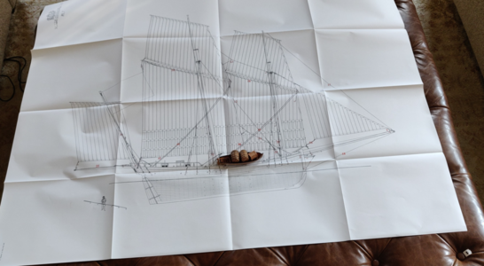
So seriously - this is going to be a big ship. I overlaid the small boat on the Ancre monograph plans. Both at the same scale.

1602374315119.png

Those plans are about 3 x 4 ft.

This is going to be an amazing heirloom that I'll leave to my kids one day.
 
I am very glad that you started your building log - and a Very good start !

Good result with the small boat - which is not part of the Le Coureur kit, but added as an add-on.
This small boat was developed already some years ago for the La Salamandre kit.
So please do not expect the same "problems" within the ships-kit - the boat has so small and fragile parts.......
Good, that you have also the planset of Jean Boudriot, which will also help you

I am looking forward to see your progress
 
I would not have expected that. It appears to be a perfect match with the small boat depicted in the Ancre monograph.
 
Making good progress:
  • Completed the keel - pretty straightforward. Tip: don't glue pieces to the sheets, just use a small bit of spray adhesive to keep them in place.

  • Completed the rear counter assembly - this was tricky. There are actually three parts to each of the curved CNC'd pieces. These are not numbered and the middle part is not indicated on the instructons or plans anywhere. Took some experimentation and very gentle sanding to finally determine that there were precision cut joints for them.

    Another important tip - carefully check the width of the seven pieces glued together at the bottom middle of the counter. I did not. When I glued them together (even clamped), they proved to be wider than the plans. I ended up having to make some adjustments I hope I don't regret later.

  • Assembled the jig - I see that Uwe did not glue his together (I think). I did as I could not things to fit snugly unless they were glued and clamped... some pieces just liked to lift up or move out of place. Seems pretty likely that I will have to carefully cut the jig into pieces to remove the ship when that time comes.

    I removed the panels which did not have precut holes for the measuring sticks later, but scored the others in case I needed to remove them.

    Another tip: If you do glue the jig, fit the keel assembly in before final gluing. It's a tight fit and you won't be able to get the keel in place without wiggling those stern frames.

    I also found that the fore keel was rubbing against the front frame, so I had to whittle a bit of clearance there.
 
HI ALL GETTING READY TO START MINE BUT WAITING UNTIL I UNDERSTAND ITEMS BETTER THEN I DO NOW,,,,A QUESTION CONCERNING THE SMALL BOAT AND FOR THE LECOURER ALSO, WHY IS EVERY ONE TRYING SO HARD TO SAND OFF THE CHAR, I LATELATELY ON ALL MY KITS AM LEAVING THE CHAR AS IS WITH MINOR SANDING INCORARATING THE CHAR AS PART OF THE FINISH, I HAVE HAD NO PROBLEM SO FAR WITH GLUE ADHEREING USING WELL BOND, AND LINECO GLUES HAVE NOT TRIED IT WITH TITEBOUND OR ELMERS YET, I JUST CAN NOT SAND OFF THE CHAR ESPECIALLY ON SMALL BUILDS LIKE THE BOAT WITH OUT SCREWING UP, JUST ME I GUESS. GOD BLESS STAY SAFE ALL DON
 
Cosmetically, I like the char in certain exposed places. However, it is effectively a pyrolytic resin so glue will likely not bond to as strongly as it would sanded wood.
 
Making good progress:
  • Completed the keel - pretty straightforward. Tip: don't glue pieces to the sheets, just use a small bit of spray adhesive to keep them in place.

  • Completed the rear counter assembly - this was tricky. There are actually three parts to each of the curved CNC'd pieces. These are not numbered and the middle part is not indicated on the instructons or plans anywhere. Took some experimentation and very gentle sanding to finally determine that there were precision cut joints for them.

    Another important tip - carefully check the width of the seven pieces glued together at the bottom middle of the counter. I did not. When I glued them together (even clamped), they proved to be wider than the plans. I ended up having to make some adjustments I hope I don't regret later.

  • Assembled the jig - I see that Uwe did not glue his together (I think). I did as I could not things to fit snugly unless they were glued and clamped... some pieces just liked to lift up or move out of place. Seems pretty likely that I will have to carefully cut the jig into pieces to remove the ship when that time comes.

    I removed the panels which did not have precut holes for the measuring sticks later, but scored the others in case I needed to remove them.

    Another tip: If you do glue the jig, fit the keel assembly in before final gluing. It's a tight fit and you won't be able to get the keel in place without wiggling those stern frames.

    I also found that the fore keel was rubbing against the front frame, so I had to whittle a bit of clearance there.
Sounds very good and very good progress..... off course we would also like to see some of your work with photos, so we can imagine it better.
During the weekend I started also the stern structure - very tricky indeed !!! did you assemble it outside the jig or with the help of this part No.9?
I will show the status of mine asap
BTW - related to the jig - I try fitted everything and than glued it together (with glue into the edges) - I think otherwise it would not be possible.
So hope to see some photos - would be interesting, especially to see the stern structure.
 
WHY IS EVERY ONE TRYING SO HARD TO SAND OFF THE CHAR, I LATELATELY ON ALL MY KITS AM LEAVING THE CHAR AS IS WITH MINOR SANDING INCORARATING THE CHAR AS PART OF THE FINISH, I HAVE HAD NO PROBLEM SO FAR WITH GLUE ADHEREING USING WELL BOND, AND LINECO GLUES HAVE NOT TRIED IT WITH TITEBOUND OR ELMERS YET, I JUST CAN NOT SAND OFF THE CHAR ESPECIALLY ON SMALL BUILDS LIKE THE BOAT WITH OUT SCREWING UP, JUST ME I GUESS. GOD BLESS STAY SAFE ALL DON
Hello Don, Cleaning the char generally for one reason: The laser beam usually set to cut the wood\plywood with a small kerf width. The actual cut is not 90 degrees to the cutting part. You are not removing the char as much as you trying to make the cutting sides even.
 
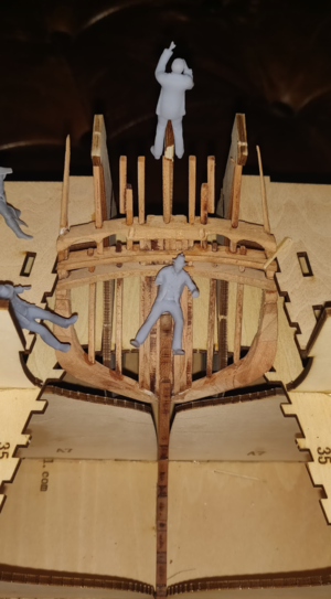
Four ghosts admiring their work on the stern.

1603239723482.png

This is a tricky piece. The seven timbers surrounding the stern post have to be carefully checked and sanded down to width as the piece is built. I did not do this and had to carefully widen the slots on the two slots of the CNC pieces above to accommodate the vertical posts surrounding the center post.

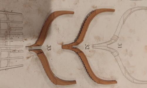
The two CNC'd pieces on the outermost left and right consist of three parts each. This is not at all clear from the manual (they don't even have part numbers) and it's a little nerve wracking carving them free from their surrounding material. But I got the job done. They aren't perfectly symmetrical... but what is?

Note that the middle post and the ones three away press fit into the jig. Wish I had known this before building as I could have made them ever so slightly more symmetrical... but again, close enough.

Haven't decided what to do with the protruding "bat fins" jutting out on the extreme right and left. Just leaving them for now but I assume they will eventually be level with the other posts. Which is good, because the upper points seem pretty fragile.
 
Working on those frames. I used a wooden edge to line up the clinker ridges. After doing about 15 of them, I realized that might not be the best approach. I'll probably have to fair a few of them to get the hang of it.

As stated before, I used a light coat of spray adhesive to hold the parts to the paper. This keeps them in place but allows me to peel them off without any glue sticking to them. It does leave a lot of dusty fingerprints behind though.

1604097025663.png

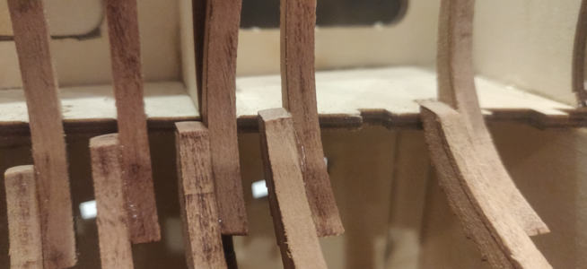
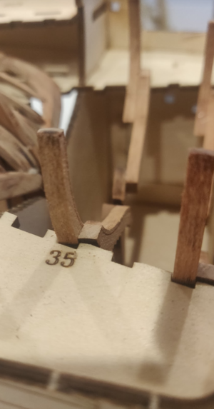
I'm having a real problem with dry fitting frame 35. The middle frame simply doesn't want to fit below the top deck of the jig. I then realized I had to fair the bottom.

1604097096590.png

1604097160215.png

1604097183443.png

This helped but not much. I'll have to determine if the bottom part of the frame needs to be shorted and faired a bit more or if the upper edge of the middle frames needs to be shaved.
 
Working on those frames. I used a wooden edge to line up the clinker ridges. After doing about 15 of them, I realized that might not be the best approach. I'll probably have to fair a few of them to get the hang of it.

As stated before, I used a light coat of spray adhesive to hold the parts to the paper. This keeps them in place but allows me to peel them off without any glue sticking to them. It does leave a lot of dusty fingerprints behind though.

View attachment 188547

I'm having a real problem with dry fitting frame 35. The middle frame simply doesn't want to fit below the top deck of the jig. I then realized I had to fair the bottom.

View attachment 188549

View attachment 188551

View attachment 188552

This helped but not much. I'll have to determine if the bottom part of the frame needs to be shorted and faired a bit more or if the upper edge of the middle frames needs to be shaved.
.
Working on those frames. I used a wooden edge to line up the clinker ridges. After doing about 15 of them, I realized that might not be the best approach. I'll probably have to fair a few of them to get the hang of it.

As stated before, I used a light coat of spray adhesive to hold the parts to the paper. This keeps them in place but allows me to peel them off without any glue sticking to them. It does leave a lot of dusty fingerprints behind though.

View attachment 188547

I'm having a real problem with dry fitting frame 35. The middle frame simply doesn't want to fit below the top deck of the jig. I then realized I had to fair the bottom.

View attachment 188549

View attachment 188551

View attachment 188552

This helped but not much. I'll have to determine if the bottom part of the frame needs to be shorted and faired a bit more or if the upper edge of the middle frames needs to be shaved.
I have encountered the same problem I aligned the upper part of the frame to the neighboring ones and then I shortened the foot of the frame a bit and also accentuated the notch on the keel
 
It may come down to that but I'll resort to that last.

Close investigation of frame 35 revealed that the clinker edges were slightly off.

1604169518706.png

I dissolved the weldbond using acetone. Took a bit of prying and a few dips before the glue dissolved.

1604169574378.png

That's when I realized my mistake. Instead of lining up the upper edge of the B piece with the bevel lines on the A and C pieces, the top/inner edges were aligned. Shucks. That means I'll probably have to redo 15 frames.

So I redid frames 33-37. Yet 35 still does not fit! It's a bit closer but still not possible to lodge it in.

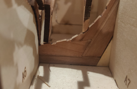
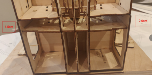
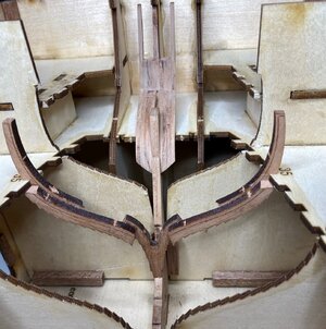
Hmm. Not going to rush this, so I inspected the jig and I found something else. I've been waiting for my pieces E1 and E2, so the back and front of the jig are still open:

1604169971399.png

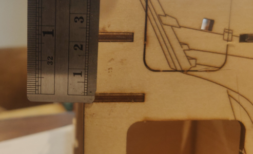
Port - 1.5cm in between the two horizontal tabs.

1604170054384.png

Starboard - 2.0cm between the two tabs:

1604170116151.png

You can see in the photo above that the port side has a small vertical slit burned where the slot should be. So we have a bad jig piece. First one I've seen in any of the CAF model build reports.

The plan here is to extend the slot downwards and release the pressure on the 2nd level of the jig so it sits perfectly horizontal. Hopefully that is the root cause behind frames 34-35 not fitting.
 
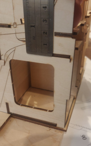
I have 19.5 mm between those 2 tabs.

Also for me it was a bit of a challenge to get frame 35 in place. I fixed it first in the top and then I slided the bottom up the ramp of the keel. I had to lift the top plate of the berth 1 - 1.5 mm in both sides simultaniously (requires 3 hands or some spacers to holdt the berth plate up while sliding the bottom of the frame backwards). The frame clicked in place with a loud sound. It was difficult to get in place but trust me, it was a walk in the park compared to getting it out again :D
IMG_0996.JPG
IMG_0995.JPG
 
Back
Top