HMS Sovereign of the Seas - Bashing DeAgostini Beyond Believable Boundaries

Joined
Jan 1, 2018
Messages
4,600
Points
688

Location
Ramsey, Minnesota, USA
HMS Sovereign of the Seas - Bashing DeAgostini Beyond Believable Boundaries - by DARIVS ARCHITECTVS

Well, I just finished La Couronne and its display case a few hours ago, and swore that I would take a break before starting another project.

That didn't happen. On to Ship #2.

Research on building HMS Sovereign of the Seas started almost immediately. I opened Issues 1-15 of the kit and started pouring through their contents, eager to work on the one ship which is the greatest inspiration above all others. The first problem reared its ugly head immediately. The false keel assembly does not include the keel itself, ending at the garboard strake of planking. I could not use my multi-position keel vice that served my so well while building La Couronne! That meant that the base jig in the DeAgostini instructions has to be built and used. The keel is attached later in assembly, and I'm afraid that it won't be strong enough to use the keel vice, and one accidental bump on the hull will break the keel off, leaving the wrecked hull rolling on the floor. I guess I'll have to be careful.

Some more observations. This model has a complete lower gun deck, unlike Corel's La Couronne, so it will be easy to replace the false half-barrel cannons with complete carriages. (Don't look at me like that, Dockattner... You may take ALL the shortcuts you want! Not THIS sailor.) Because the kit instructions are scattered across 135 packages in magazines, the steps for assembling multiple similar items like cannons are also scattered, and there are no blueprints or rigging drawings to refer to that give you the complete picture of how elements like lines, decorations and other landmarks used in measuring are positioned, relative to each other and the hull overall. This is quite different than working from the two general arrangement drawings and seven rigging drawings that helps you classify and keep track of what you are working on, and where something goes.

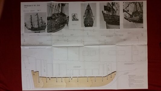
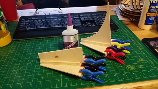
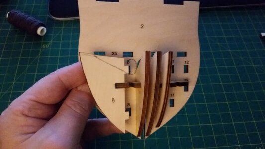
Just to get something done, the first frame pieces of the bow were glued together, and some wood metal "L" brackets for making the base jig were purchased. There is still one more piece of wood to purchase before the base jig can be completed and the false keel assembled. Since I wanted to use those GORGEOUS Amati cast decorations on this model, the problem remains whether or not they would fit because the scales between the Amati and DeAgostini models are slightly different. Laying the false keel bulkheads on the Amati plans shows that they may actually be close enough to allow use of most of the Amati decorations. Each decoration, Amati or DeAgostini, will have to be chose based on how close to the Payne description of the decorations they are. Perhaps in some cases neither will work, and scratch built decorations will have to be made, which I do not have the patience, tools or talent to do. Carving is a slow, high risk task for me. Too much can go wrong. After all, I'm an engineer (Architectus in Latin), not an artist.

Many things will be replaced in this white metal casting, plywood ridden, arguably accurate DeAgostini kit. LET THE BASHING BEGIN.

001 Ship Name.jpg

It looks like somebody broke the sprit topmast, or it that just he camera lens effect?
002 Ship Picture.jpg

This is NOT what the kit build would look like. This is the scratch built Italian made model that the simplified kit approximates, and falls short of:
HMS SOVEREIGN OF THE SEAS.JPG

003 Start Bow Assembly.jpg

004 Compare DeAgostini Frame to Amati Plan.jpg
 
Last edited:
Kurt,

On board for your SoS - bound to be superbly executed and well researched.

Cheers,
One of the big things that concern me is the hull shape. Herr Röler on Das Wettringer Modellbauforum is building a wood-tone SotS based on the DeAgostini kit also, and has truly set the bar regarding modifying it with internal frames and changes to the decks and bulwarks. His model will influence mine greatly.

Link: Röler's SotS <--cool stuff here, guys!

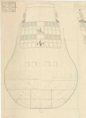
What concerns me at the moment is hull shape. The DeAgostini kit frame bulkhead look round and do not have the curves based on Anthony Deane's Doctrine of 1670, as described in Jon McKay's book, Sovereign of the Seas 1637. The 19th century drawing from the Royal Museums in Greenwich below shows the hull shape as originally constructed. Note the curves and flat spots in the body form of the lower hull. This cross section was arrive at by a traditional use of various circle radii to get those curves, all described in Deane's Doctrine. DeAgostini's hull form does not follow this shape, but I think it should, since even though it was described at a later time, the ruled used for hull construction would probably not have changed substantially like other features in ship design, such as riggings and fixtures. The question is, how do I modify the DeAgostini frames to this more complicated shape? A comparison between the DeAgostini hill form and the one described in John McKay's book will be made, and changes made to conform more to McKays's study, since he uses Deane's rules for body form. Werner on SegelSchiffs Modellbau forum is in the process of making and perfecting a computer model of the hull shape for HMS SotS and his study is yielding some impressive drawing results.

1605719313361.png
 
Last edited:
Hi Kurt,

Fantastic new project, also have this kit in the attic but think I will never build it and start the SOTS from scratch in the future.
Your bashed deagostini kit will be a daunting task, heads off for that.

I will follow closely.

Guess you also had a look at Nigels @NMBROOK bashed deagostini SOTS, which is truly great.
 
Can't wait to see another Kurt masterpiece. Eagerly awaiting to follow. Thanks for sharing. You have a unique way of explaining intricate tasks that one can almost imagine what you are doing even with just words alone.
 
HMS Sovereign of the Seas - Bashing DeAgostini Beyond Believable Boundaries - by DARIVS ARCHITECTVS

Well, I just finished La Couronne and its display case a few hours ago, and swore that I would take a break before starting another project.

That didn't happen. On to Ship #2.

Research on building HMS Sovereign of the Seas started almost immediately. I opened Issues 1-15 of the kit and started pouring through their contents, eager to work on the one ship which is the greatest inspiration above all others. The first problem reared its ugly head immediately. The false keel assembly does not include the keel itself, ending at the garboard strake of planking. I could not use my multi-position keel vice that served my so well while building La Couronne! That meant that the base jig in the DeAgostini instructions has to be built and used. The keel is attached later in assembly, and I'm afraid that it won't be strong enough to use the keel vice, and one accidental bump on the hull will break the keel off, leaving the wrecked hull rolling on the floor. I guess I'll have to be careful.

Some more observations. This model has a complete lower gun deck, unlike Corel's La Couronne, so it will be easy to replace the false half-barrel cannons with complete carriages. (Don't look at me like that, Dockattner... You may take ALL the shortcuts you want! Not THIS sailor.) Because the kit instructions are scattered across 135 packages in magazines, the steps for assembling multiple similar items like cannons are also scattered, and there are no blueprints or rigging drawings to refer to that give you the complete picture of how elements like lines, decorations and other landmarks used in measuring are positioned, relative to each other and the hull overall. This is quite different than working from the two general arrangement drawings and seven rigging drawings that helps you classify and keep track of what you are working on, and where something goes.

Just to get something done, the first frame pieces of the bow were glued together, and some wood metal "L" brackets for making the base jig were purchased. There is still one more piece of wood to purchase before the base jig can be completed and the false keel assembled. Since I wanted to use those GORGEOUS Amati cast decorations on this model, the problem remains whether or not they would fit because the scales between the Amati and DeAgostini models are slightly different. Laying the false keel bulkheads on the Amati plans shows that they may actually be close enough to allow use of most of the Amati decorations. Each decoration, Amati or DeAgostini, will have to be chose based on how close to the Payne description of the decorations they are. Perhaps in some cases neither will work, and scratch built decorations will have to be made, which I do not have the patience, tools or talent to do. Carving is a slow, high risk task for me. Too much can go wrong. After all, I'm an engineer (Architectus in Latin), not an artist.

Many things will be replaced in this white metal casting, plywood ridden, arguably accurate DeAgostini kit. LET THE BASHING BEGIN.


It looks like somebody broke the sprit topmast, or it that just he camera lens effect?


This is NOT what the kit build would look like. This is the scratch built Italian made model that the simplified kit approximates, and falls short of:
Hey Kurt,
If you don't want to wade through all the printed instruction books you can download .pdf versions here: https://www.model-space.com/us/build-sovereign-of-the-seas-full-kit.html and then click on the 'download' button. My DeAg Vasa didn't even arrive with the printed instruction books - but that wasn't a problem for me since they wouldn't have shown me what shortcuts to take anyway!!!
Looking forward to watching you own this thing!
Only a few of the issues, including the mast plans, are available at that link. A good start at least. I spent the day opening Issues 1-45 and stuffed the magazines into the binders. The materials remain in numbered plastic bags for easy locating. The next step seems to be pulling out the hull frames, studying them, and comparing the body form to the hull shape information from McKay (sourced from Deane), and what Herr Röler did with his Deagostini SotS model conversion. It's a real puzzle drawing info from so many sources, deciding which features may be the most accurate or at least the most attractive, then bashing or replacing the kit parts. Modifications that are already planned include:

1) Rounding the front bulkhead of the forecastle to the correct shape.
2) Researching the correct cannon carriages for the various guns and replacing them as necessary.
3) Changing the overall shape of the transom to match the Payne painting of Peter Pett as close as possible.
4) Changing the bottom stern to a "demi-rounded" shape that has a hard line bend combined with a round tuck, a blend of a round and square tuck.
5) Before assembling the hull frames, compare them to similarly located frames in the McKay version of the hull.
6) Replace all crappy blocky blocks with Model Expo beautiful or Falkonet blocks.
7) Replace the crappy pre-made sails with custom sails similar to those on La Couronne, but better.
8) Making the internal deck support structures and and cannon port structures similar to what Herr Röler did, probably not as nicely, but a good approximation.
9) Install a full lower gun deck with gun carriages instead of the fake gun barrels (shut up, Dockattner!) ;)
10) And a bunch of other stuff.
 
Last edited:
Hi Kurt,

Fantastic new project, also have this kit in the attic but think I will never build it and start the SOTS from scratch in the future.
Your bashed deagostini kit will be a daunting task, heads off for that.

I will follow closely.

Guess you also had a look at Nigels @NMBROOK bashed deagostini SOTS, which is truly great.
DEFINITELY will look at Nigel's DeAgostini SotS!
 
Only a few of the issues, including the mast plans, are available at that link. A good start at least. I spent the day opening Issues 1-45 and stuffed the magazines into the binders. The materials remain in numbered plastic bags for easy locating. The next step seems to be pulling out the hull frames, studying them, and comparing the body form to the hull shape information from McKay (sourced from Deane), and what Herr Röler did with his Deagostini SotS model conversion. It's a real puzzle drawing info from so many sources, deciding which features may be the most accurate or at least the most attractive, then bashing or replacing the kit parts. Modifications that are already planned include:

1) Rounding the front bulkhead of the forecastle to the correct shape.
2) Researching the correct cannon carriages for the various guns and replacing them as necessary.
3) Changing the overall shape of the transom to match the Payne painting of Peter Pett as close as possible.
4) Changing the bottom stern to a "demi-rounded" shape that has a hard line bend combined with a round tuck, a blend of a round and square tuck.
5) Before assembling the hull frames, compare them to similarly located frames in the McKay version of the hull.
6) Replace all crappy blocky blocks with Model Expo beautiful or Falkonet blocks.
7) Replace the crappy pre-made sails with custom sails similar to those on La Couronne, but better.
8) Making the internal deck support structures and and cannot port structures similar to what Herr Röler did, probably not as nicely, but a good approximation.
9) Install a full lower gun deck with gun carriages instead of the fake gun barrels (shut up, Dockattner!) ;)
10) And a bunch of other stuff.
Be sure to open each Pack from the website - if they are presented like the Wasa each .pdf has 10-15 stages.
 
Okay... After assembling the bow support structure, the bowsprit hole was to the correct location, shifting it to starboard so the base of the bowsprit doesn't interfere with the the foremast. The hole was cut using a diamond bit and Dremel, and a chunk of spare plywood was used to fill in the original hole, but that wasn't really necessary. The farthest piece on the starboard side had a triangular shaped section taken off to make room for the bowsprit, exactly the same profile as the support immediately to port of it. This was a feature of 17th century men of war, because they typically had the foremast located farther forward on the forecastle than later ships.
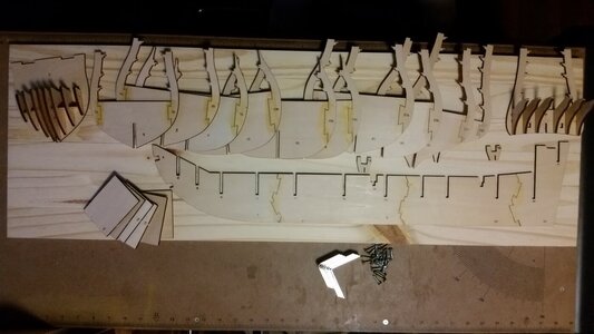
arts for the false keel jig were fabricated. A stern support and a bow support made from plywood was assembled. The next step was digging through the packages and getting the frames assembled so they can be studied against other sources for the correct shape. Then the false keel jig was assembled, taking the wood and hardware purchased earlier, plus the stern and bow support pieces created earlier according to the kit instructions.

Next, reinforcement squares of plywood will be glued over the joints in the false keel assembled, lending more strength to the backbone of the ship.

005 Begin Bow Frame Assembly.jpg

006 Move Bowsprit Hole to Correct Location to the Right of the Foremast.jpg

007 Fabricate Parts for False Keep Jig Supports for Bow and Stern.jpg

008 Assemble False Keel Jig Supports.jpg

009 Assemble Frames and Stern Assembly.jpg

010 Glue False Keel Sections Together and Assemble Jig to Support Them.jpg
 
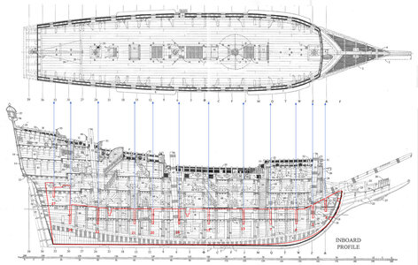
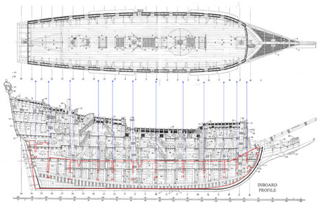
The first step in analyzing the DeAgostini hull for to the John McKay hull is to compare the false keel frame to the cross section of McKay's version. The sternpost was used as a reference point to position image of the kit's false keel. You will note that the masts locations are quite different, and the angle of the transom is different. Scaling up the false keel draws the two masts closer to matching McKay's ship as shown in the second picture below, which may be a more correct scale for the false keel. As a consequence though, fewer of the kit frames line up easier with McKay's numbered/lettered cross section drawings. So, it us more difficult to compare McKay's cross sections to DeAgostini's model bulkhead frames. The location of DeAgostini frames are indicated by the blue lines and arrows. The location of the forecastle beakshead bulkhead lines up better in the second picture also because the false keel was also moved rearward a small amount. The DeAgostini kit will place the lower gun deck height half way up higher to the next deck up than the McKay design, which will be hard to resolve.

Since the McKay transom remains very wide as it tapers toward the keel, and has a square tuck, the entire rudder is located in an eddy of turbulence, and water will not flow in a laminar fashion over the rudder, making it ineffectual for turning the ship. The DeAgostini model has a round tuck, and the hull is very narrow at the sternpost, and much of the rudder's surface area is in the water stream, so it makes an effective rudder. If you guys have any thoughts after looking at this, let me know. Maybe you could suggest another scale and alignment between the Mckay and DeAgostini profile which will make them match better.

Composite Cross Section.jpg

Composite Cross Section 2.jpg
 
Kurt, I didn't see that anyone had mentioned it, but I just purchased 'Sovereign of the Seas 1637' by John McKay from USNI. I'm using it as a reference for my HMS Prince project, but thought you might find it extremely useful in your construction journey. It has pretty much every detail of the 1637 version of the ship you would need to assist in your construction. All the best, Matt
 
Kurt, belay my last...just noted a McKay reference in an early entry. Good luck with the build. All the best, Matt
 
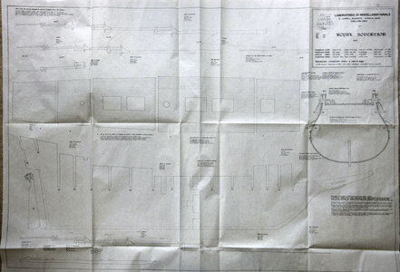
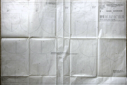
Hi Kurt, This ship is my next project after I finish my Amerigo Vespucci, probably just after Xmas. It is a kit from about 1970, CARTA AUGUSTA, more of a scratch build unlike modern kits. I can see that the plans differ from most other offerings but I thought that you just might find something helpful in them, you can’t have too many sources

Sorry about the quality of the photos but the light indoors at the moment is very poor and the drawings are very fine lined.


Ken

001.jpg

002.jpg


003.jpg

004.jpg
 
I wouldn't worry too much about McKay. You might have a look at the reviews of this book on Amazon, and particularly the review by Frank Fox, who is the preeminent naval historian on ships of this era. I would add to those comments that the McKay's idea of starting with Deane wasn't a very good one.

We can compare the width of the floor and the dimensions of the sweeps given by Phineas Pett, the ship's designer (Pett's sweeps are given in an article in a 1919 issue of The Mariner's Mirror by R.C. Anderson), to the floor and sweeps we can compute from Deane, and from the Treatise on Shipbuilding (ca. 1620-1625). As you can see in the attached photo, the Treatise is closer to Pett's sweeps than is Deane.

Notice that the photo shows a midship bend with four sweeps. You can make the argument that it really had five sweeps. The sweep omitted by Pett is the hollowing sweep. The length of this sweep is given in a letter written to King Charles by Pennington in 1635, and are reproduced in the Autobiography of Phineas Pett, which you can find for free on line. I should add that the opinion of WG Perrin (the editor of Pett's autobiography) is that Pennington's plans were used instead of Pett's. That's not right, but it would take a lot of pixels to explain why.

Also, please remember that the attachment is a photo. I don't have the gear to properly shoot pictures of plans, so there is some distortion in the width at the top. Nevertheless, you get the idea.

The plans from about 1800 are also problematic. They don't show any dead rising, which the Sovereign almost certainly had. Pett build the Royal Prince without it, and was so roundly criticized by shipwrights, that it was a mistake he wouldn't repeat. If Werner's plans are the ones I'm thinking of, they also have this problem (for that matter, so does the photo I attached, so view it as more of a cartoon than an actual plan).

The bottom line here is that you pretty much have to draw your own plans to get it right (or, at least close to right). This is a MAJOR undertaking that involves hundreds of little decisions that never seem to make it into books. It's taken me about 2,000 hours just to come up with a reasonable sheer plan, but but it's so messy that I'd be embarrassed to show it to anyone, and I still have the body plan to do.

Not trying to be a killjoy here. Have fun with the model. That's what really counts.Comparing_Midship_Bends.png
 
I wouldn't worry too much about McKay. You might have a look at the reviews of this book on Amazon, and particularly the review by Frank Fox, who is the preeminent naval historian on ships of this era. I would add to those comments that the McKay's idea of starting with Deane wasn't a very good one.

We can compare the width of the floor and the dimensions of the sweeps given by Phineas Pett, the ship's designer (Pett's sweeps are given in an article in a 1919 issue of The Mariner's Mirror by R.C. Anderson), to the floor and sweeps we can compute from Deane, and from the Treatise on Shipbuilding (ca. 1620-1625). As you can see in the attached photo, the Treatise is closer to Pett's sweeps than is Deane.

Notice that the photo shows a midship bend with four sweeps. You can make the argument that it really had five sweeps. The sweep omitted by Pett is the hollowing sweep. The length of this sweep is given in a letter written to King Charles by Pennington in 1635, and are reproduced in the Autobiography of Phineas Pett, which you can find for free on line. I should add that the opinion of WG Perrin (the editor of Pett's autobiography) is that Pennington's plans were used instead of Pett's. That's not right, but it would take a lot of pixels to explain why.

Also, please remember that the attachment is a photo. I don't have the gear to properly shoot pictures of plans, so there is some distortion in the width at the top. Nevertheless, you get the idea.

The plans from about 1800 are also problematic. They don't show any dead rising, which the Sovereign almost certainly had. Pett build the Royal Prince without it, and was so roundly criticized by shipwrights, that it was a mistake he wouldn't repeat. If Werner's plans are the ones I'm thinking of, they also have this problem (for that matter, so does the photo I attached, so view it as more of a cartoon than an actual plan).

The bottom line here is that you pretty much have to draw your own plans to get it right (or, at least close to right). This is a MAJOR undertaking that involves hundreds of little decisions that never seem to make it into books. It's taken me about 2,000 hours just to come up with a reasonable sheer plan, but but it's so messy that I'd be embarrassed to show it to anyone, and I still have the body plan to do.

Not trying to be a killjoy here. Have fun with the model. That's what really counts.
Ooops! I made a mistake in my previous post. I should have said the Pennington supplied the sweep above the breadth. He doesn't give the hollowing sweep. Nobody does. That one is pretty much guess work.

Sorry about my mistake.
 
This will be a fascinating project. I am somewhat amazed that DeAgostini markets the kit with pictures of an entirely scratch-built model; that hardly seems fair, or honest. Nevertheless, Roller’s log in the German forum shows to quite an amazing degree what can be done with this kit.

I wish you luck, and I will gladly follow along.
 
Back
Top