
-

SUBSCRIBE TO SHIPS IN SCALE TODAY!
The beloved Ships in Scale Magazine is back and charting a new course for 2026!
Discover new skills, new techniques, and new inspirations in every issue.
NOTE THAT OUR NEXT ISSUE WILL BE July/August 2026 -

Win a Free Custom Engraved Brass Coin!!!
As a way to introduce our brass coins to the community, we will raffle off a free coin during the month of August. Follow link ABOVE for instructions for entering.
You are using an out of date browser. It may not display this or other websites correctly.
You should upgrade or use an alternative browser.
You should upgrade or use an alternative browser.
Kingfisher 1770 1:48 POF [COMPLETED BUILD]
- Thread starter dockattner
- Start date
- Watchers 144


Hi @trussben,Beautiful work.
Would the shot locker hinges not be on top of the cross beam, instead of vertical on the front face? As per TFFM.
View attachment 425818
I re-read my response to you, and I fear I might have come across as dismissive of your very accurate/helpful/well-informed post. When I was building the well house I "over shaped" the part that merges with the shot locker. I had already invested quite a bit of time on that part and when I recognized that I would need to place the hinges in the wrong place I chose to just accept the mistake and carry on. I am not attempting to build the perfect TFFM swan class ship.
BUT: if I was trying to build the perfect TFFM swan class ship your post would have saved the day! So, THANK YOU for your keen attention to detail and feeling welcome to offer a suggestion for improving this build. I do rely on people like you who have far more experience and knowledge than I do to keep my project on track. While I won't be correcting this error, I have been correcting other mistakes pointed out by forum members. Keep the suggestions coming! And I apologize for the brevity of my original post.
As prompted by friends on the forum I have added some details to the well house (bolts on the hinges, and nails/treenails on the boards):


Yes, the bolts on the hinges are not straight - but since I had to do these freehand (having neglected to include them originally) this was the best I could do.
I am still uncertain if I should be adding 'fasteners' on these build-out elements (there are a lot of walls and such to be added). I struggled adding these nails to the well house (they are 0.40 mm drilled holes filled with wood filler). I can't make wooden pegs small enough. But I wanted to at least try something.
Your thoughts?
Last edited:
I mentioned in an earlier post that I wanted to take a shot at fabricating rudder hinges (pintles and gudgeons). The kit instructions called for a combination of plastic for the hinge parts and black paper/card stock for the straps. On the Vasa I make some faux hinges out of brass shim stock, but they were a pretty weak attempt.
Of course, fabricating actual hinges would mean that I needed to learn how to solder. Not exactly neurosurgery but my experience with soldering was limited to home repair/electronics.
My approach required adding brass bar stock (1.5 mm x 2.0 mm) to some thinner brass stock that would form the straps (1.5 mm x 0.3 mm).


I then did some preliminary shaping:


At this point I felt like I had something to work with...
Of course, fabricating actual hinges would mean that I needed to learn how to solder. Not exactly neurosurgery but my experience with soldering was limited to home repair/electronics.
My approach required adding brass bar stock (1.5 mm x 2.0 mm) to some thinner brass stock that would form the straps (1.5 mm x 0.3 mm).
I then did some preliminary shaping:
At this point I felt like I had something to work with...
Next, I needed to drill holes for the bolts that would hold the straps to the rudder and the hull. To that end I made a little jig:


I then used epoxy to add the pins to the pintles (I could have soldered these pins but that would have required a lower melting temperature solder (than I had used previously) and I doubted I could pull that off):


That done, I burnished/blackened the parts and completed the rudder side of the transaction:


And just in case you think this was a linear experience...I learned that brass can melt...and that it's possible to solder the pins you are using to hold pieces into place onto (inside) the parts you are soldering...

I feel blessed that you would visit on occasion!
I then used epoxy to add the pins to the pintles (I could have soldered these pins but that would have required a lower melting temperature solder (than I had used previously) and I doubted I could pull that off):
That done, I burnished/blackened the parts and completed the rudder side of the transaction:
And just in case you think this was a linear experience...I learned that brass can melt...and that it's possible to solder the pins you are using to hold pieces into place onto (inside) the parts you are soldering...
I feel blessed that you would visit on occasion!
Love those two additions, mon ami!
For the hinges, as we say "The Devil is not that scary as on the paintings" Great job soldering, and the entire rudder assembly, love those bolts and their perfectly round heads, well made!
Kurt Konrath
Kurt Konrath
Great work on the hinges and rudder, the details to the shot locker and well house are amazing as well, up to your great standards! ")

Gorgeous innovative work, which I have come to expect of paul.Next, I needed to drill holes for the bolts that would hold the straps to the rudder and the hull. To that end I made a little jig:
View attachment 426367
View attachment 426368
I then used epoxy to add the pins to the pintles (I could have soldered these pins but that would have required a lower melting temperature solder (than I had used previously) and I doubted I could pull that off):
View attachment 426369
View attachment 426370
That done, I burnished/blackened the parts and completed the rudder side of the transaction:
View attachment 426357
View attachment 426358
View attachment 426359
View attachment 426360
View attachment 426361
View attachment 426362
View attachment 426364
View attachment 426365
View attachment 426366
And just in case you think this was a linear experience...I learned that brass can melt...and that it's possible to solder the pins you are using to hold pieces into place onto (inside) the parts you are soldering...
View attachment 426371
I feel blessed that you would visit on occasion!
Can I ask please
1: What is the jig fixation device used to hold the wood and parts for drilling?
2: After you soldered the pintles how did you shape and polish them? The solder joins are invisible!
3: You mention burnishing the brass. Is this blackening with Brass Black or similar?
4: What is your burnishing method/recipe with the brass to avoid the powder like coating?
Thank you for your detailed post, and the how-to pearls for the ludidtes like myself to elevate our skills.
Satisfied consumer of your eye candy.
michael

Paul, great idea. I will take it into service, with your permissionI mentioned in an earlier post that I wanted to take a shot at fabricating rudder hinges (pintles and gudgeons). The kit instructions called for a combination of plastic for the hinge parts and black paper/card stock for the straps. On the Vasa I make some faux hinges out of brass shim stock, but they were a pretty weak attempt.
Of course, fabricating actual hinges would mean that I needed to learn how to solder. Not exactly neurosurgery but my experience with soldering was limited to home repair/electronics.
My approach required adding brass bar stock (1.5 mm x 2.0 mm) to some thinner brass stock that would form the straps (1.5 mm x 0.3 mm).
View attachment 426352
View attachment 426353
I then did some preliminary shaping:
View attachment 426354
View attachment 426355
View attachment 426356
At this point I felt like I had something to work with...
I think there is no way to make it better
The hinges are extremely good - very good metal works (and wood of the rudder)
Bravo my friend - first class work
 you are getting 3 "likes" from my side
The hinges are extremely good - very good metal works (and wood of the rudder)
Bravo my friend - first class work
you are getting 3 "likes" from my sideFrom me, you get a OK!. Looks very nice, Paul.As prompted by friends on the forum I have added some details to the well house (bolts on the hinges and nails/treenails on the boards):
View attachment 426348
View attachment 426349
Yes, the bolts on the hinges are not straight - but since I had to do these freehand (having neglected to include them originally) this was the best I could do.
I am still uncertain if I should be adding 'fasteners' on these build-out elements (there are a lot of walls and such to be added). I struggled adding these nails to the well house (they are 0.40 mm drilled holes filled with wood filler). I can't make wooden pegs small enough. But I wanted to at least try.
Your thoughts?
Regards, Peter
Last edited:
I mentioned in an earlier post that I wanted to take a shot at fabricating rudder hinges (pintles and gudgeons). The kit instructions called for a combination of plastic for the hinge parts and black paper/card stock for the straps. On the Vasa I make some faux hinges out of brass shim stock, but they were a pretty weak attempt.
Of course, fabricating actual hinges would mean that I needed to learn how to solder. Not exactly neurosurgery but my experience with soldering was limited to home repair/electronics.
My approach required adding brass bar stock (1.5 mm x 2.0 mm) to some thinner brass stock that would form the straps (1.5 mm x 0.3 mm).
View attachment 426352
View attachment 426353
I then did some preliminary shaping:
View attachment 426354
View attachment 426355
View attachment 426356
At this point I felt like I had something to work with...
And for these hinges, you do not get only a OK, it also a WOW, Paul. A nice piece of small construction and soldering.Next, I needed to drill holes for the bolts that would hold the straps to the rudder and the hull. To that end I made a little jig:
View attachment 426367
View attachment 426368
I then used epoxy to add the pins to the pintles (I could have soldered these pins but that would have required a lower melting temperature solder (than I had used previously) and I doubted I could pull that off):
View attachment 426369
View attachment 426370
That done, I burnished/blackened the parts and completed the rudder side of the transaction:
View attachment 426357
View attachment 426358
View attachment 426359
View attachment 426360
View attachment 426361
View attachment 426362
View attachment 426364
View attachment 426365
View attachment 426366
And just in case you think this was a linear experience...I learned that brass can melt...and that it's possible to solder the pins you are using to hold pieces into place onto (inside) the parts you are soldering...
View attachment 426371
I feel blessed that you would visit on occasion!
Practice makes perfection.
Regards, Peter
Jim, Kurt, Heinrich, Michael, Sasha, Mirek, Uwe, Peter, Stephan - and to many others for the likes - my sincere thanks!
Hello Michael,Gorgeous innovative work, which I have come to expect of paul.
Can I ask please
1: What is the jig fixation device used to hold the wood and parts for drilling?
2: After you soldered the pintles how did you shape and polish them? The solder joins are invisible!
3: You mention burnishing the brass. Is this blackening with Brass Black or similar?
4: What is your burnishing method/recipe with the brass to avoid the powder like coating?
Thank you for your detailed post, and the how-to pearls for the ludidtes like myself to elevate our skills.
Satisfied consumer of your eye candy.
michael
Q1: this is the Compound Table that comes with the Proxxon Mill - though I purchased a second one to also use with a small drill stand. It is designed to fit onto Proxxon machines/tools.
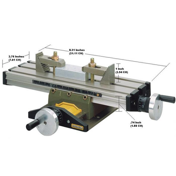
MICRO Compound Table KT 70
For precise milling, boring, drilling or grinding operations as well as positioning. The optimal attachment when working with the Drill Stand MB 140/S, the Bench Drill Machine TBM 115 or the Machine Vice MS 4. One set of step clamps and clamping accessories are included. Technical data:Table...
proxxon-us-shop.com
Q2: I did some initial shaping using a disc sander. The rest was done with files.
Q3: Casey's Brass Black
Q4: This one is more a work in progress for me. I am very familiar with the frustration of getting a powdery black layer that flakes off. My current approach is as follows (though I suspect it will change as I learn more). First, I thoroughly clean the parts (rotary tool, sandpaper, etc.) and then I drown the parts in white vinegar (30 - 60 minutes seems about right) and after this the parts must not be touched by fingers - only tweezers. Then I drown the part in Brass Black that has been quite diluted (not exactly sure of the formula - it is at least 50% water right now, maybe as much as 80%???) I use the same Brass Black over and over. In it's diluted state the blackening/burnishing takes a bit longer (maybe 60 seconds). Rinse off the part in running water and set on a paper towel to dry. I then wipe down the part using a soft cloth or Q-tip (there will be a fine powder on it) and assess. You can go back into the Brass Black if you want it darker. I think the magic happens when you dilute the Caseys and allow the burnishing to take more time. Again, still learning...

Paul, as a retired farrier, blacksmith, all I can say is WOW! What a great job on the pintles, and what a quick learning curve. Great attention to detail.
Last edited: