• LUCZORAMA SHIPWRECK SCAVENGER HUNT GIVEAWAY. 4 Weeks of Fun • 1 Legendary Prize ((OcCre’s Fram Ship)) • Global Crew Welcome!
    **VIEW THREAD HERE**

HMS Litchfield (48) 1695 1:64 scale

Joined
May 9, 2024
Messages
2,916
Points
588

This has been an off and on project for several years and has a way to go but I thought some members might find it interesting and perhaps useful in some ways.
I prepared plans based on the contemporary plans from RMG as well as scantlings from the contracts for her sister ships.

If anyone checking in on this log has questions, critiques, suggestions and so forth, please do not hesitate to post them, all input is welcome.

Litchfield (Lichfield) 1695

PARTICULARS

The following is from the British Navy List

Shipwright: William Stigant, Portsmouth Dockyard

Ordered: 16 November 1693

Launched: 4 February 1695 (modern dating) The launch date on the list of British Navy List shows 1694. I spotted this and thought it odd that all other information I found gave a launch date of 4 February 1695. This discrepancy is due to the old calendar in England had the new year starting on March 24th which was Lady’s Day (one of the year’s financial quarter days, when rents were paid; the others being Midsummer’s day, Michaelmas, and Christmas Day).

Type: 48 gun fourth-rate ship of the line. The number of guns for the 130 foot class, of which Litchfield is a part, varied from 46 to 50 guns.

Tons burthen: 682

Length on the gun deck: 130 feet 3 inches NB: The contracts for the Severn, Burlington Romney and Colchester specify 130 feet, and the contract for Jersey specifies 132 feet. The Jersey was several years after the other mentioned ships and it is surmised that the extra two feet of length on the gun deck were needed.

Length of the keel: 107 feet 7 inches

Beam: 34 feet 7.5 inches

Depth of hold: 13 feet 6 inches

Armament: 48 guns of various weights of shot in the Commonwealth pattern.

Twenty-two 8 feet, 6 inch long twelve pounders on gun deck

Twenty-two 8 feet long six pounders on upper deck

Four 7 feet long six pounders on the quarter deck (based on number of gun ports on drawing from NMM J4030)

Possibly two, 8 feet, 6 inch long six pounders on forecastle by approximately 1702 (based on descriptions found in The History of English Sea Ordinance, by Adrian Caruana)

Other 50 gun ships of the 130 foot group:

Weymouth 1693

Colchester 1694

Romney 1694

Lincoln 1695

Coventry 1695

Harwich 1695

Severn 1695

Burlington 1695

Pendennis 1695

Blackwall 1696

Guernsey 1696

Nonsuch 1696

Warwick 1696

Dartmouth 1698

Hampshire 1698

Winchester 1698

Salisbury 1698

Carlisle 1698

Worcester 1698

Jersey 1698

Tilbury 1699

GENERAL NOTES
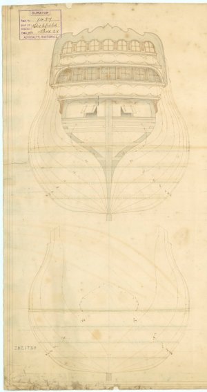
This project is based mainly on scantlings from the Severn, Burlington, Romney, Colchester, and Jersey contracts and drawing J4030 from the Royal Museum Greenwich which was prior to her rebuild to the 1719 Establishment in 1730 shown on RMG drawing J4031. Drawing J4030 may or may not reflect some changes she underwent when in ordinary between the time she was launched and taken apart and rebuilt. Stylistically it appears to be mostly from the last decade of the 17th century long before her rebuild. There is a date of 1730 penciled on the drawing (possibly by someone at RMG), or perhaps at a time that some new lines were drawn on the original drawing in blue. I communicated with RMG about this and they had no explanation other than it was probably a mistake due to there being a separate drawing of Litchfield 1730. The location of the channels and split wales are as normally seen from the 17th century to about the time of the 1719 Establishment. In discussing drawing J4030 with a well know expert on English ships he noted that the ink wash on the wales is very likely pre-18th century or very early 18th century indicating the drawing could very well be close to how she looked when launched.

NOTE: There are a few discrepancies between the drawing and contracts. Where these involved dimensions, I prepared spread sheets of scantlings based on the contracts which are precise. One major discrepancy is the number of gun ports. The drawing shows eleven upper deck gun deck ports and eleven lower gundeck ports whereas the contract calls for eleven upper deck gun ports and twelve lower gun deck ports. In The 50 Gun Ship by Rif Winfield, he points out very clearly that the actual number of guns varied. Regarding Litchfield, he refers to “The 1690s vessels, the 48s”. This would account for eleven ports on each side of the lower deck, eleven on each side of the upper deck, and two on each side of the quarter deck.

For me there was a big question as to how ornate were the galleries and other decorations, including painting and carvings. Wreaths are known to have been eliminated by order of the Admiralty sometime in 1703 so were possibly, if not likely, to be found on Litchfield when launched. It can be argued that Litchfield would have had a more ornate design of her galleries than indicated in the basic design on drawing J4030. Some contemporary models show very ornate galleries and sterns for ships circa 1690 to 1700, others do not. I drew two options on the plans for the construction and design of the galleries before deciding which I would use.

The stern ornamentation are from my own imagination. I have taken pieces from various contemporary models of the era and incorporated a few of my own ideas on carvings that yielded the designs on the drawings I prepared for the build.

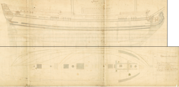
J4030 drawing. The original is at scale 1:48. The model in this log is being built to 1:64
1728315704217.png
 
Last edited:
I was going include some of her history but as I have accumulated nearly 11 typed pages of information, it would likely be boring to most readers. If anyone is interested I can add it here or PM it.

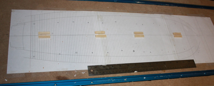
STATION LINES and FRAMING GUIDE
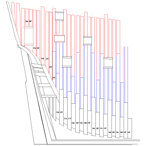
Station lines on the Litchfield drawing J4030 are as usually seen on contemporary drawings with numerals aft and letters forward of the center. It is interesting that some others, including a drawing of Antelope, 1703 show the station lines beginning with the numeral “1” near the bow them going to “21” near the fashion piece. The body plan gives the hull shape at each station and these were used to draw the frames and prepare the building board framing guide. The Room and Space for Litchfield 1695 was 2 feet 2 inches.
1728381180922.png

1728381376813.jpeg

KEEL, STEM, STERN POST, RISING WOOD, KEELSON, DEADWOOD &C.
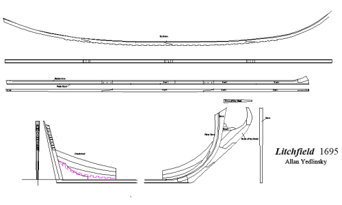
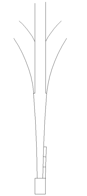
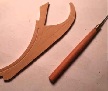
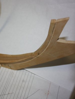
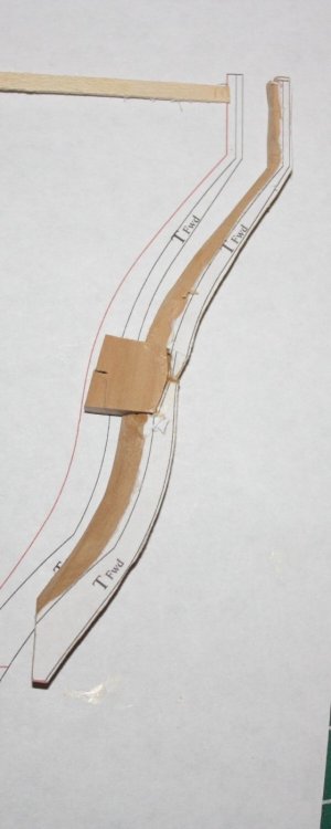
Scale drawings of the various keel, stem, post and deadwood pieces were completed using drawing J4030 and the scantlings from the contract. The below shows the keelson, keel, deadwood aft and knee of the head forward. Note that the keel, the sternpost and knee of the head are all tapered, they were never the same thickness and/or breadth for their entire lengths.
1728382364232.png

Keel
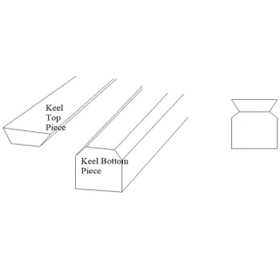
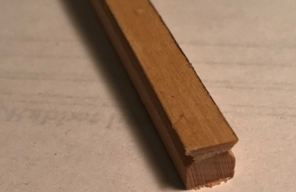
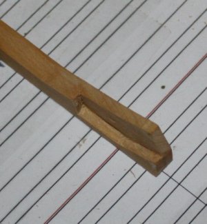
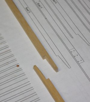
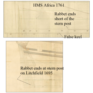
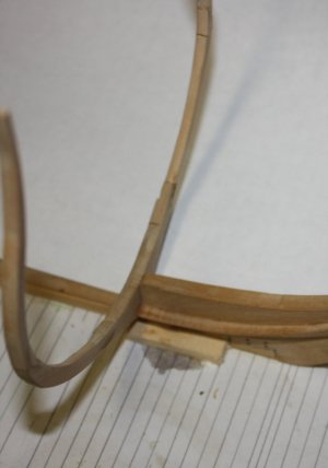
Based on drawing J4030, the rabbet on the keel ends at the fore side of the stern post, rather than further forward as seen on later ships. It should transition in angle to match the angle of the frames, then ending as an “L” shape as it nears the sternpost. I experimented in making the keel as the rabbet ends exactly at the top of the keel which was very hard to achieve with a shaped cutter or other hand tools. I made the keel in two layers, with the thickness coming to the center of rabbet. The angle of the rabbet was then shaped along its length on each piece and then glued together. Extra care was taken toward the stern to be sure the rabbet ended in an “L” shape as the breadth of the garboard strake is near vertical as it runs aft. 1728383192147.png1728383213901.png


Stavo per includere parte della sua storia, ma poiché ho accumulato quasi 11 pagine di informazioni dattiloscritte, probabilmente sarebbe noioso per la maggior parte dei lettori. Se qualcuno è interessato posso aggiungerlo qui o PM it.

LINEE DI STAZIONE e GUIDA ALL'INQUADRATURA
Linee di stazione sul Litchfield il disegno J4030 è come di solito si vede sui disegni contemporanei con numeri a poppa e lettere a prua del centro. È interessante che alcuni altri, tra cui un disegno di Antilope, 1703 mostrano le linee della stazione che iniziano con il numero “1” vicino alla prua che vanno a “21” vicino all'opera di moda. La pianta della carrozzeria dà la forma dello scafo in ciascuna stazione e questi sono stati utilizzati per disegnare i telai e preparare la guida dell'intelaiatura del pannello da costruzione. La stanza e lo spazio per Litchfield 1695 erano 2 piedi e 2 pollici.
View attachment 476038

View attachment 476045

CHIGLIA, GAMBO, PALO DI POPPA, LEGNO CRESCENTE, KEELSON, LEGNO MORTO & C.
I disegni in scala dei vari pezzi di chiglia, stelo, palo e legno morto sono stati completati utilizzando il disegno J4030 e le scarse parti del contratto. Il sotto mostra il paramezzale, la chiglia, il legno morto a poppa e il ginocchio della testa in avanti. Si noti che la chiglia, il montante di poppa e il ginocchio della testa sono tutti affusolati, non hanno mai avuto lo stesso spessore e/o larghezza per tutta la loro lunghezza.
View attachment 476053

Chiglia
Basato sul disegno J4030, la battuta sulla chiglia termina sul lato anteriore del montante di poppa, anziché più in avanti come visto sulle navi successive. Dovrebbe passare in angolo per adattarsi all'angolo dei telai, per poi terminare con una forma “L” quando si avvicina al montante di poppa. Ho sperimentato la realizzazione della chiglia poiché la battuta termina esattamente nella parte superiore della chiglia, cosa molto difficile da ottenere con una fresa sagomata o altri utensili manuali. Ho fatto la chiglia in due strati, con lo spessore che arriva al centro di rabbet. L'angolo del rabbetto è stato quindi modellato lungo la sua lunghezza su ciascun pezzo e poi incollato insieme. È stata prestata particolare attenzione verso poppa per essere sicuri che il rabbet terminasse a forma di “L” poiché la larghezza del fasciame della riga è quasi verticale mentre corre a poppa. View attachment 476059View attachment 476060


Thumbsup
 
Note that the main species used for this model is Castello and kiln dried winter holly which was purchased in boards then cut and thicknessed as needed.

The forward end of the keel has a boxing joint which varied in shape at times. In the later 7th and early 18th century it was often coaked. As this would not be seen in the end I chose to leave out the slot and tenon. In the words of Peter Goodwin in The Construction and Fitting of the English Man of War, page 10, "....individual builders had their own eccentricities, possibly handed down from their forefathers." In this case it applies to the model builder. :)

The finished joint on the keel was made with hand chisels and is seen below. If anyone is interested in super fine micro chisels, I cannot recommend those from Mihail Kirsanov highly enough. mihail.kirsanov@mail.ru

1728409826108.jpeg
From the contract regarding the keel and false keel:

Keeles to be of Elme (Not More than in Three Pieces) and to be fourteen Inches Square in the Midships with Scarphs Four Foot Four Inches Long at least and Each Scarph Tabled and laid with Tarr & Hair, to be well bolted with Six Bolts by an Inch Auger.

False Keeles To be Three Inches thick of Elme laid with Tarr & Hair and well fastened with Treenails Spikes and Staples.


The up and down dimension of the keel would remain at 14 inches its entire length, but there is no mention of the breadth fore and aft in the contract. To find these dimensions I used the body plan. The scarphs on the keel are vertical while those of the keelson are horizontal as usually seen.

1728413343588.jpeg
As mentioned above, the rabbet ends at the aft end of the keel at the stern post rather than farther forward as was done on RN ships in later years. The following shows the difference. The contract specifies a 3 inch thick false keel but it is not shown on the profile plan of Litchfield as was done on later plans such as HMS Africa (64) 1761 below..

1728430383898.png
 
Last edited:
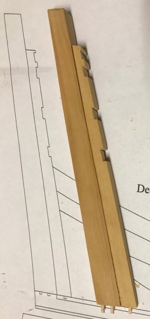
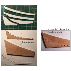
The deadwood aft was a little challenging to get to the shape needed. It tapers in thickness from where the half frames rest, down to the inside breadth of the keel accounting for the planking sitting snug in the rabbet.
Allan

1728477300937.png1728477786959.png
 
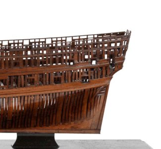
The knee of the head is similarly constructed of multiple pieces. A significant difference with later era ships are the overall shape and where the frames sit on the The photo below of a contemporary model from 1703 shows the frames ending at the stem rather than at the rabbet. The introduction of cant frames may have created the need for this change although I have not yet found any contemporary information to support or refute this.
1728901802528.pngModel 1703


1728902296538.pngModel 1725

1728901857115.png

1728902194184.jpeg
 
Assembly of the stem, false stem and knee of the head on the keel came next.
1728987274169.jpeg
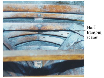
I am not a fan of pre-assembling sections but I tried this for the stern with the post, inner post and transoms with good results. Note that there are full transoms and half transoms. These can be seen in the contemporary model in the next photo below.
1728987526705.png
The following is from the contract written in 1695 for Severn and Burlington:
Main Transome To be Twelve Inches and the Lower Transomes Ten Inches Thick and to lye Eighteen Inches one from another and to Fill the space between them on Each side the Post with a sufficient Number of halfe Transomes of Such substance that their upper and Lower Edges May lye Two Inches at least Cleare of the Whole Transomes To give Space for aire.

The dado cuts in the inner post indicate the location of full transoms with half transoms in between.1728988092563.jpeg

In researching this area I found a contemporary model with a stylized design that was interesting.
1728987943461.png

The next photo is the transom assembly with the fashion pieces and the aft half frame.
1728989786675.jpeg
 
I drew up all the frames based on the body plan and scantlings from the contract. The following is the transcription on the framing from the contract
Timber and Roome To be Twenty Four Inches.
Floor Timbers To be Thirteen Inches Fore and aft and Fourteen Inches up & Downe Upon ye Keele And of Such Lengths in the Floor of the Ships that their Heads May Lye Eighteen Inches at least above the Bearing thereof by a Streight line from the Bottome of the Keele and to be Eleven Inches (Moulded) in and out at the Wrongheads and Ten Inches Wrought in the Length of the Floor and before and abaft the Same to be Nine Inches Wrought in and out and Every Other Floor Timber To be Bolted Through the Keele with one Bolt by an Inch and Eighth auger.
Lower Futtocks To fill the Roomes Full and Workmanlike for the Strength of the Frame below And to be Twelve Foot long at least & to be Chocked Downe Within Twenty Inches of the Keele.
Upper Futtock Head to take the Lower Cill of the Ports in the Midships and the Heele of the Top Timber The Lower Edge of the Gundeck Clamps Within Board and Wale Without Board. To be Ten Inches fore and aft and Eight Inches in and out at the Breadth and to Stand an Inch and halfe Apart for Aire.
Top Timbers to be Three Inches in and out aloft. And the Whole Frame to be well Chocked with good Sound Timber.
Hawse Pieces To place Two Substantiall Hawse Pieces on Each Side the Stem to be Twenty Two Inches Broad Each Piece at least.


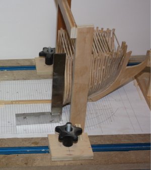
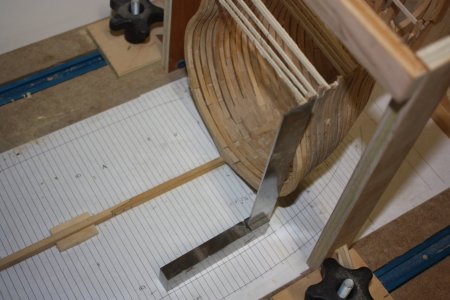
The actual framing for Litchfield is mostly straight forward as there were no cant frames used until about 20 years later. Each frame is assembled and PARTIALLY shaped before being raised on the keel. I use a building board with sliding gantry that makes things a lot easier.

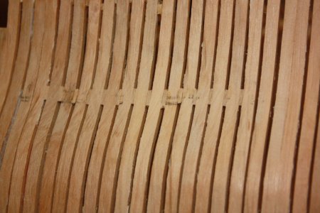
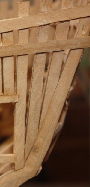
There was some question for me as to whether the futtocks were chocked together or scarphed. After researching various sources, including drawings by Richard Endsor in The Master Shipwright's Secrets and The Resoration Warship I decided chocks would be appropriate at least on the lower futtocks with scarphs for the top timbers. There is evidence that scarphs may have been used so I had a choice. The forward and aft most frames made the use of chocks a bit of a challenge. As the frames are square and they are heavily shaped the cut for the chocks and the chocks had to be carefully shaped as well. This angle, which is dynamic to match the shape of the frame, can be seen in the photo below.
1729335229286.jpeg

For the frames' wood, I used Castello and made batts in various thicknessed based on the scantlings. As usual for me I print the frames on label paper then cut out the futtocks and stick the paper pieces onto the wood to be used. I used to glue these on but found that they can stretch and otherwise distort where as self adhesive label paper is much easier to work with. A partially shaped half frame shows this below.
1729335563994.jpeg
Forward most full frame
1729335713169.jpeg
 
Framing can be as maddening at times but since I have gone to using a home made building board with a gantry it is much easier to get things right. The design for my set up is thanks to builder, author and friend Ed Tosti (HMS Naiad and Young America books) A good set of squares are not expensive and very useful at various parts of the build. I print out a framing guide and secure it to the building board with white glue as it is easy to moisten and remove once the hull is framed. In addition to making sure things are squared up the guide prevents cumulative error. A small error in location on one frame is easy to compensate for knowing where the frame line is to be, but it can accumulate drastically over 100 frames, so the guide is extremely useful in preventing this from happening.

Temporary pieces of wood are temporary glued to the top timbers to be sure frame does not spread or get squeezed during the framing erection process.

1729937865086.jpeg
1729938492476.jpeg

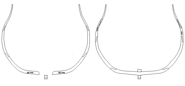
Alternating frames did not touch the keel until about 1710. (The Construction and Fitting of the English Man of War, page 14) As this would not be seen once the model is planked and decked I decided to add a chock to these partial frames. The drawing of two adjacent frames below shows the full frame and half frames. When half frames were to be used, all of the full frames are first erected then the half frames installed within 20 inches of the keel and secured with chocks and bolts to the full frames.

1729940035068.png

From the contract

Floor Timbers To be Thirteen Inches Fore and aft and Fourteen Inches up & Downe Upon ye Keele And of Such Lengths in the Floor of the Ships that their Heads May Lye Eighteen Inches at least above the Bearing thereof by a Streight line from the Bottome of the Keele and to be Eleven Inches (Moulded) in and out at the Wrongheads and Ten Inches Wrought in the Length of the Floor and before and abaft the Same to be Nine Inches Wrought in and out and Every Other Floor Timber To be Bolted Through the Keele with one Bolt by an Inch and Eighth auger.

Lower Futtocks To fill the Roomes Full and Workmanlike for the Strength of the Frame below And to be Twelve Foot long at least & to be Chocked Downe Within Twenty Inches of the Keele.

Upper Futtock Head to take the Lower Cill of the Ports in the Midships and the Heele of the Top Timber The Lower Edge of the Gundeck Clamps Within Board and Wale Without Board. To be Ten Inches fore and aft and Eight Inches in and out at the Breadth and to Stand an Inch and halfe Apart for Aire.

Top Timbers to be Three Inches in and out aloft. And the Whole Frame to be well Chocked with good Sound Timber.
 
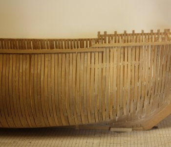
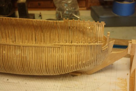
Some framing progress photos follow. The frames are made of Castello boxwood. There were no cant frames at the time Litchfield 1695 was built and as usual the futtocks are reduced in their siding dimension as well as the in and out (moulded) dimension as follows from the contract:

Floor Timbers To be Thirteen Inches Fore and aft and Fourteen Inches up & Downe Upon ye Keele And of Such Lengths in the Floor of the Ships that their Heads May Lye Eighteen Inches at least above the Bearing thereof by a Streight line from the Bottome of the Keele and to be Eleven Inches (Moulded) in and out at the Wrongheads and Ten Inches Wrought in the Length of the Floor and before and abaft the Same to be Nine Inches Wrought in and out and Every Other Floor Timber To be Bolted Through the Keele with one Bolt by an Inch and Eighth auger.

Lower Futtocks To fill the Roomes Full and Workmanlike for the Strength of the Frame below And to be Twelve Foot long at least & to be Chocked Downe Within Twenty Inches of the Keele.

Upper Futtock Head to take the Lower Cill of the Ports in the Midships and the Heele of the Top Timber The Lower Edge of the Gundeck Clamps Within Board and Wale Without Board. To be Ten Inches fore and aft and Eight Inches in and out at the Breadth and to Stand an Inch and halfe Apart for Aire.

Top Timbers to be Three Inches in and out aloft. And the Whole Frame to be well Chocked with good Sound Timber.
Allan

Note that in the area where the channels will be mounted there were chocks between the frames so there are no worries of the bolts attaching the channels to the hull will not fall in open space between the frames.
1730455155607.jpeg
Half frames aft
1730454849993.jpeg
Showing cut out for the pumps.
1730455082903.jpeg

1730455371435.jpeg
1730455432987.jpeg
Note how thin the top timbers are moulded at their heads, 3 inches (0.047" -1.2mm) They were thicker in later years; 4.5" in the Establishments into the second half of the 18th century and 6.5" given in by David Steel in The Elements and Practice of Naval Architecture which presumably goes from the late 18th century into the 19th century.
 
Last edited:
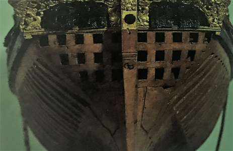
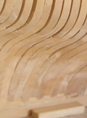
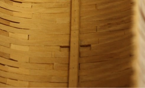
The framing at the stern is the typical set of angled partial frames. The planks in the photo at this point are temporary battens. Temporary cross pieces are added to maintain the shape and location of the frames and the battens removed for final sanding of the frames.


1730806679967.jpeg
 
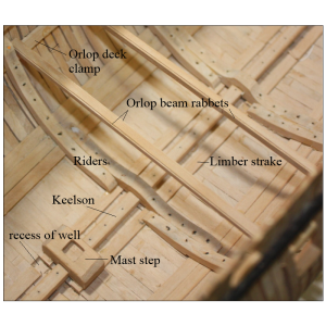
The internal parts are pretty straight forward. The floor riders and futtock riders were sized and bolted in place per the contract. There are couple orlop beams in the photo as well showing the rabbet on each side of the beam in which the deck planks sit. Unlike deck planks on ships with platforms and the upper decks, orlop deck planks rested in these rabbets and were not fixed in place so they could be easily removed for access into the hold. Note that I mistakenly used 8 bolts on the upper arms rather than the seven called for in the contract.

The Kelson Not to have More than Four Pieces and to Run fore and aft and to Over launch the Scarphs of the Keele. To be Fourteen Inches Up and Downe and Fifteen Inches Broad Scored Downe Upon the Timbers an Inch and halfe at least. The Scarphs to be Four Foot Long at least and to be Bolted Through Every Other Timber and Through the Keele by Bolts by an Inch and eighth Auger.

Limber Board To be Two Inches & a halfe Thick and Fourteen Inches Broad on Each Side the Kelson.

Floor and Futtock Ryders To Fay and Fasten Three Bends of Floor and Lower Futtock Ryders. The Floor Ryders to be Fifteen Inches fore and Aft Eleven Inches Up and Downe Upon ye Keele and Eleven Inches at ye Wrongheads. To be Twenty Foot long at least and Bolted with Seven Bolts in Each Arme by an Inch & Eighth Auger. The Futtock Ryders To be Fourteen Inches fore and aft and Eleven Inches Thick and to be Thirteen Foot long Each and Bolted with Nine Bolts of the same Size.

1731066560993.png
 
Last edited:
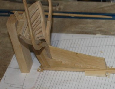
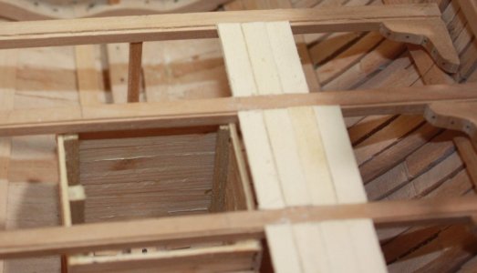
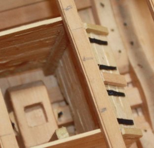
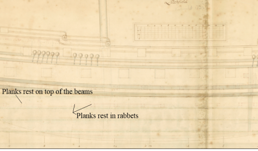
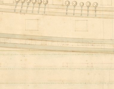
More platform beams and some planking in place along with the lodging knees, well and shot lockers. It is difficult to see but the pins and wedges can be seen by the mast step. Note in the Litchfield contemporary drawing below that two sections have the planking resting in rabbets for easy removal for access to stores in the hold. One section has the planking resting and trennaled to the top of the beams. It is a bit difficult to see, but it is a bit more clear on the enlargement of the drawing in the last picture below.
Allan
1731759183670.jpeg
1731759585452.jpeg
1731758846238.png1731759051416.jpeg
 
Last edited:
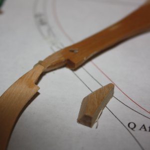
Back
Top