Granado CAF kit by Janos

Joined
Jul 2, 2013
Messages
1,239
Points
433

Location
Sydney
Apparently I stepped over to the dark side... )):= after many scratch builds and "old" type bashed kits I try myself in this very promising CAF kit. I ordered it as soon as Tom reported it being ready, a couple of weeks ago and it arrived today, after only 5 days delivery time from China, which is not bad at all.

I started reading Uwe's log (thanks for it here too, Uwe!) and I still did not decide whether or not I am going to build a separated hull. I will also look into other building logs of Granado.

I am not going to write a proper building log but I try to post a few pictures here and there about my progress.

MERRY CHRISTMAS to everyone!

János
 
Dear Janos. There is some poetic justice that I should be the first to comment on your proposed build. I know that the combination of your expertise and build ability coupled to a superb kit will result in a very special model. All of the best!
 
Apparently I stepped over to the dark side... )):= after many scratch builds and "old" type bashed kits I try myself in this very promising CAF kit. I ordered it as soon as Tom reported it being ready, a couple of weeks ago and it arrived today, after only 5 days delivery time from China, which is not bad at all.

I started reading Uwe's log (thanks for it here too, Uwe!) and I still did not decide whether or not I am going to build a separated hull. I will also look into other building logs of Granado.

I am not going to write a proper building log but I try to post a few pictures here and there about my progress.

MERRY CHRISTMAS to everyone!

János
Merry Christmas Janos. Looking forward to this build. Cheers Grant
 
Schönen Dank, Heinrich, thanks, Grant!
I started on the kit, currently numbering all small laser cut parts for identification. Then comes the crate and I still don't know whether to build this model in one or with a separated hull. If building without separation I could add mast, yards and rigging (I have the AoS book), or with a separated hull I could show all the internal details, which is very tempting, and having a separated hull Granado might fit into my glass cupboards. So there are arguments for both solutions, I just have to decide...
Merry Christmas to everyone!
János
 
I have a slow (very slow relative to Uwe) progress with preparations. I marked and separated all laser cut parts and arranged the parts for the frames into numbered envelops. Currently I am removing the laser char and preparing the frame parts to assemble the frames.
Yes, and I continue reading Uwe's great description - currently at Page 19.
János
 
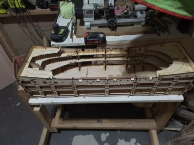
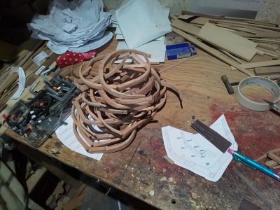
In the mean time I prepared all the frames. I glued their parts on the top of a copy of the drawn frames together and followed the contours as much as I could but I am still afraid whether they will come out right. Then I sanded all frames 'blindly' ie. only following the laser marks. It will turn out if this was the right approach. So I have a pile of sanded frames - se picture - and now I take a big breath before the next step. I side-stepped the second step in the manual - the assembly of the keel. I had some difficulties by assembling it - not able to identify some of the parts - but now there is no excuse before I have to put the keel together and then trying the frames on it. The cradle is assembled already so here we come, frames!
János

20250226_195706.jpg

20250226_195655.jpg
 
The next step: I dry-assembled the ribs between 8 and 47 onto the keel. This was not as straightforward as I hoped but I managed after lots of small corrections on the keel. I did not follow the manual fully, as I assembled and glued the cradle completely before installing the ribs - but this turned out to be OK. Now come the bow- and aft-sections and it looks like I reached the end of the easy run. So a birds-eye view of the current state:

20250308_191340.jpg

A few lessons learnt until now:

- The cradle is an awesome help, very nicely constructed too. I attached it to my roll-tilt table which I made for SoS earlier.

- It looked a good idea to remove all laser cut parts from the sheets before assembling the ribs but it turned out not to be. The reason I was doing this that I wanted to 'economise' the sanding process by doing it in bulk. This was OK for the ribs but I hit a snag at the assembly of the keel parts - and will have the same difficulty at the assembly of the bow and aft too. It would have been better not to remove the parts from the sheets so to finding and identifying the parts could have been quicker. I lost much time to search for parts in those envelopes. Fortunately I did this preparation only for Session 1 so I will do it differently for the next sessions. I found it a small but genius trick that the sheets name (3A, 4A, etc) mirrors the thickness of the sheets.

In the main time I silently gave up the idea of separating the hull into two. I just could not find the consistent references for the cutting line in the manual (except the bow and the stern) so I went on the easy way.

The build is much slower then what Uwe produced but I enjoy every step of it.

János
 
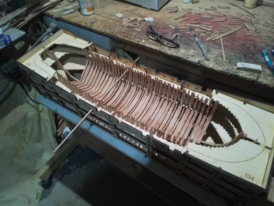
The front- and rear frame groups are now put together with some discrepancies. During the installation of the false keel and neighbouring parts I hit the first big hurdle. The inside (false) keels length did not come up right. If I put all the parts together the length was about 12mm longer that the room in the ship. I am sure I made all parts to the necessary dimensions and I can't explain why this happened. At the end I had to leave part 6a4 out and had to insert a custom made part instead. (I asked Tom about this issue but he answered only generally so it was no help - probably I was expecting too much.)
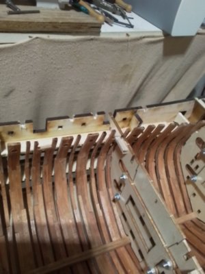
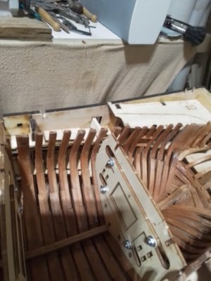
Beyond this I still have the problem that the frames are too narrow so at the top of the cradle there is a gap of about 2-6 mm between the frames and the slot in the cradle. I made the frames on top of copies of the frame drawings so there should not be a discrepancy like this but still there it is. So not only the outside of the frames won't provide a smooth surface but also the inside of them will be rough. I can't assess the outside surface now because of the cradle but I am sure there will be an uneven surface. The inside has the same problem and I tried to rectify it somewhat by sanding the frames. Dodgy work!
On a personal note I will continue putting the kit together but to be honest I lost the enthusiasm I had at the beginning. A very expensive failure.
János

1000010243.jpg

1000010240.jpg
 
Beyond this I still have the problem that the frames are too narrow so at the top of the cradle there is a gap of about 2-6 mm between the frames and the slot in the cradle. I made the frames on top of copies of the frame drawings so there should not be a discrepancy like this but still there it is.
Hey Janos. Don't let these problems discourage you. Discrepancies you report don't look like a major issue at all. So many modellers got the very same problem on this model as well on many others, more or less. Even with the far simplier Hoy that issue occurred quite often to all the modellers. You can easily fill the gaps forcing the frames into their jig's pockets and keep them there nailing some pins into the jig and using rubber bands as belts between these and the pins. If you pre-soak the frames and then dry them up with an hairdryer in between, the alteration will come almost permanent or easily faired when you will be installing the beamshelves. Cheers... and keep on going!
 
Last edited:
Hey Janos. Don't let these problems discourage you. Discrepancies you report don't look like a major issue at all. So many modellers got the very same problem on this model as well on many others, more or less. Even with the far simplier Hoy that issue occurred quite often to all the modellers. You can easily fill the gaps forcing the frames into their jig's pockets and keep them there nailing some pins into the jig and using rubber bands as belts between these and the pins. If you pre-soak the frames and then dry them up with an hairdryer in between, the alteration will come almost permanent or easily faired when you will be installing the beamshelves. Cheers... and keep on going!
Wonderful advice.
 
The front- and rear frame groups are now put together with some discrepancies. During the installation of the false keel and neighbouring parts I hit the first big hurdle. The inside (false) keels length did not come up right. If I put all the parts together the length was about 12mm longer that the room in the ship. I am sure I made all parts to the necessary dimensions and I can't explain why this happened. At the end I had to leave part 6a4 out and had to insert a custom made part instead. (I asked Tom about this issue but he answered only generally so it was no help - probably I was expecting too much.)
Beyond this I still have the problem that the frames are too narrow so at the top of the cradle there is a gap of about 2-6 mm between the frames and the slot in the cradle. I made the frames on top of copies of the frame drawings so there should not be a discrepancy like this but still there it is. So not only the outside of the frames won't provide a smooth surface but also the inside of them will be rough. I can't assess the outside surface now because of the cradle but I am sure there will be an uneven surface. The inside has the same problem and I tried to rectify it somewhat by sanding the frames. Dodgy work!
On a personal note I will continue putting the kit together but to be honest I lost the enthusiasm I had at the beginning. A very expensive failure.
János

View attachment 509880

View attachment 509883
Good afternoon Janos. These are not insurmountable problems. I agree with Albert that with some elastic bands you can pull the frames into the slots. When you fit the internal stringers these will keep the frames in symmetry. The changes you made to accommodate the keel 12mm variant sound like they will work. Your work so far looks good so I would keep at it. Cheers Grant
 
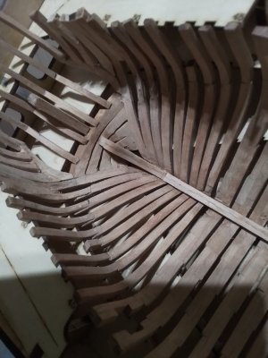
I just hit another snag as I started Section 2. The locating templates are a great idea but the are not precisely enough worked out. All of them are interfering with the gunport sills. No. 1, 2 and 3, where only the bottom sills are installed (as per manual) the templates had to be modified to fit (Picture 1). No 4 is more complicated, it not only had to be modified, but also be assembled in situ because of the to sills. (Picture 2). Quite an exercise.

BTW the templates would interfere with that certain 'pasted on' 5x2mm strips (also the manual pictures show this interference) but overriding the manual I did not install those strips yet.

I don't want to be always negative but I think these comments might be of help for someone else in his journey. I already expressed my gratitude towards the precise laser work and to the attention to detail and these comments still stay.

János

1000010247.jpg1000010248.jpg
 
Well, probably my last report about this struggle. I hit a snag yesterday and I don't know yet how can I get out of this hole.
As the first step of Session 2, I started installing the deck shelves (I am not sure about the name). According to the manual, picture 10, it is about the parts 3B- B1, 3A-B2 and 3A-B3 which create a chain from the stem to the aft. As there is no reference point or mark given, I glued in the foremost front parts (3B-B1) to the frames (and managed to break both of them due to the aggressive bend so I had to make new ones), and then the next one midship. At the aft end (3A-B3) I realised that this part is about 30mm (29 to be exact) longer than it supposed to be. Seeing this I started looking for reference, which I did not find, but I realised that the notches on the midship part (3A-B2) are not there where they should be on the manual pictures. So it looks in hindsight that I should have started from the aft and just cut that surplus length from the front piece? But I did not. So I either have to break all these parts from the rib and start new (but what is that length discrepancy?) or throw the whole thing against the wall.
Again, lesson learnt, a very expensive, failed build.
János
Greetings, Janos

I was rather surprised while reading your post. I have no doubts about your skills and experience, I saw your models in the past. I cannot imagine you couldn't come up with a game plan. You are an experienced scratch builder, and the term 'bashing the kit' should be familiar to you. We all know that kits have flaws and discrepancies, and unfortunately, they don't depend on their costs and manufacturer names.

I am sure you will come up with a plan, to avoid the future ship model becoming a kamikaze plane hitting your wall. Isn't overcoming the challenges make our hobby more interesting? Don't give up, mon ami! Prove that you can do it!!!
Thanks, Jim
I wrote to Tom yesterday and asked him whether or not he can help me with those part and with a reference dimension to locate them. Plan B will be that I am packing Session 2 and 3 together and send them back for a refund. He did not answer yet.
János
 
Days pass and Tom still did not reply at all. Frustrated and more and more disappointed by the day...
János
 
The front- and rear frame groups are now put together with some discrepancies. During the installation of the false keel and neighbouring parts I hit the first big hurdle. The inside (false) keels length did not come up right. If I put all the parts together the length was about 12mm longer that the room in the ship. I am sure I made all parts to the necessary dimensions and I can't explain why this happened. At the end I had to leave part 6a4 out and had to insert a custom made part instead. (I asked Tom about this issue but he answered only generally so it was no help - probably I was expecting too much.)
Beyond this I still have the problem that the frames are too narrow so at the top of the cradle there is a gap of about 2-6 mm between the frames and the slot in the cradle. I made the frames on top of copies of the frame drawings so there should not be a discrepancy like this but still there it is. So not only the outside of the frames won't provide a smooth surface but also the inside of them will be rough. I can't assess the outside surface now because of the cradle but I am sure there will be an uneven surface. The inside has the same problem and I tried to rectify it somewhat by sanding the frames. Dodgy work!
On a personal note I will continue putting the kit together but to be honest I lost the enthusiasm I had at the beginning. A very expensive failure.
János

View attachment 509880

View attachment 509883
Hi Janos. l have recently finished this kit. Can l suggest a possible reason for the ribs not fitting correctly into the top slots of the jig. There are 2 contact points for the frames midships and 3 contact point at the bow and stern on each side of the jig. The front edges of the notches that contact the ribs are square, where the ribs are curved, so a slight angle has to be filed into the notch to allow for the curve, or the rib will not fit into the notch properly and will held off enough to allow the gap at the top. Also the notches are very tight and this may be holding the ribs away and preventing them seating properly
 
Back
Top