• "LUCZORAMA SHIPWRECK SCAVENGER HUNT GIVEAWAY RAFFLE"
    Luczorama is proud to launch a 4-week scavenger hunt giveaway packed with creativity, laughs, and nautical nonsense. Explore historic ships, solve easy clues, and have some fun with fellow builders. Complete weekly missions to earn raffle entries — the more you join in, the better your chance to win a Fram model ship by OcCre!
    **VIEW RULES HERE**

Granado CAF kit by Janos

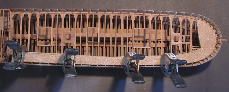
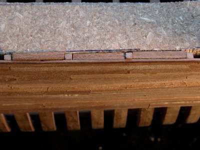
I just hit another snag as I started Section 2. The locating templates are a great idea but the are not precisely enough worked out. All of them are interfering with the gunport sills. No. 1, 2 and 3, where only the bottom sills are installed (as per manual) the templates had to be modified to fit (Picture 1). No 4 is more complicated, it not only had to be modified, but also be assembled in situ because of the to sills. (Picture 2). Quite an exercise.

BTW the templates would interfere with that certain 'pasted on' 5x2mm strips (also the manual pictures show this interference) but overriding the manual I did not install those strips yet.

I don't want to be always negative but I think these comments might be of help for someone else in his journey. I already expressed my gratitude towards the precise laser work and to the attention to detail and these comments still stay.

János

View attachment 510481View attachment 510480
The templates have to be used before the gun port sills are installed
 
Well, probably my last report about this struggle. I hit a snag yesterday and I don't know yet how can I get out of this hole.
As the first step of Session 2, I started installing the deck shelves (I am not sure about the name). According to the manual, picture 10, it is about the parts 3B- B1, 3A-B2 and 3A-B3 which create a chain from the stem to the aft. As there is no reference point or mark given, I glued in the foremost front parts (3B-B1) to the frames (and managed to break both of them due to the aggressive bend so I had to make new ones), and then the next one midship. At the aft end (3A-B3) I realised that this part is about 30mm (29 to be exact) longer than it supposed to be. Seeing this I started looking for reference, which I did not find, but I realised that the notches on the midship part (3A-B2) are not there where they should be on the manual pictures. So it looks in hindsight that I should have started from the aft and just cut that surplus length from the front piece? But I did not. So I either have to break all these parts from the rib and start new (but what is that length discrepancy?) or throw the whole thing against the wall.
Again, lesson learnt, a very expensive, failed build.
János
I got the height and fore/aft position of the deck clamps by taking measurements from the 1:1 side drawings supplied with part 2 of the kit.
 
Last edited:
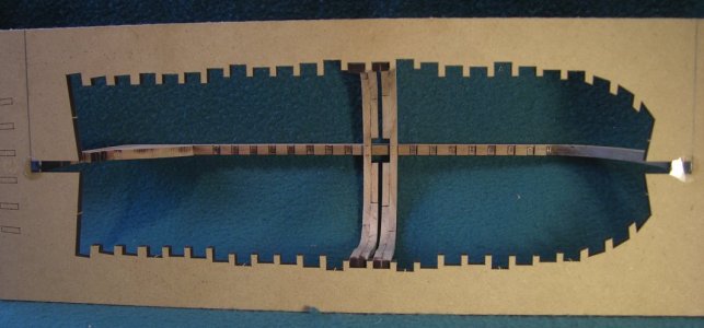
the problem you were having with the frames not fitting into the jig notches is common issue, i have seen it many times with builders building Hahn ship in a jig.
As said in a post, at this point all you can do is use rubber bands and pull the top of the frames into the jig notch. hopefully you will not break the frames. You can leave the frames as is but the problem will compound itself because the cap rails will now be off. Also the frames are no longer being held in place by a jig so to keep everything in line try using spacers between the frames.

it is not builders error it is a problem of tolerance being lost in translation from the original design and cad drawings to the laser cutting, printed plans and the accuracy of the builder. if you are going to build frames to fit a jig you have to use a jig to build the frames.
 
i know it is too late at this point but these kits with their fancy jigs actually do not work. Here is what has to be done
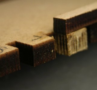
notice the dark ends of the frames they fit tight to the jig


CN9813.jpg

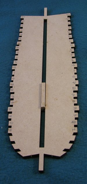
the only way to get the frames to fit tight to the jig is to use the jig

by using the inside of the jig laser cur a grove, the size of the keel that will fit a keel size block

644.jpg


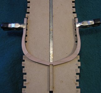
build the frames on this jig by lining up the top of the frames to the outside of the jig

9637.jpg

looking close you can see how the frame lines up with the jig notch well. it is not the actual notch it is the inside or negative of the framing jig notch. Depending on the laser cut there is a kerf so the inside of the notch will be smaller that the actual notch in the framing jig. but that kerf is small enough you can pull the frame into the notch or slightly overlap the frame.

SCN9649.jpg

these kits expect you to freehand the building of frames over a printed pattern which may or may not be a perfect match to the actual laser cut jig. As you found out the hard way. What was not taken into account from a design point is the kerf of the laser cut, the original CAD design, the printed patterns and the fact no one freehands a build to zero tolerance.
 
i have found myself in the same predicament with a build. The easy way is to pull the fames into the notches with a rubber bands and glue the deck clamps in place to hold the frames in place. In my case the frame would break before i could pull them in line.
What i did was trace the shape of the cap rail and cut out a form using a baton on the outside i pulled the frames in line. This minimized the amount i had to pull each frame in line.

brace.jpg

the problem is with the frames not being held in place with a jig they are floating fore and aft and in and out. So i glued a spacer between each frame creating a solid wall.

fill pieces.jpg
 
Last edited:
Thanks, Dave!
I used the rubber bands but at the moment there are still gaps. I hope it will sort it out itself when the deck clamps will be on.
János
 
Thanks, Dave!
I used the rubber bands but at the moment there are still gaps. I hope it will sort it out itself when the deck clamps will be on.
János
Try to soak them and then to apply more tension to the upper futtock while warming the whole single frame with an hair dryer. As already hinted, you can keep permanently the frames into their jig's socket using beams as spacers (as done in real wooden boat building) utill deck clamps would do the job.
Cheers a keep on modelling!
 
the only way to get the frames to fit tight to the jig is to use the jig

I found most of your technical commentary a little difficult to follow, Dave, but this sentence seems to be the heart of the matter. Having supplied a jig with the kit, why would the designer call for the frames to be built elsewhere? Can this issue be traced back to the ship kit’s perennial Achilles' heel, poor drafting and translation of the instruction manual?

I have a POF Le Requin on hand, which has plans but essentially no instructions. I’ve considered that a failing but perhaps it’s a lucky break.

Thanks, Dave!
I used the rubber bands but at the moment there are still gaps. I hope it will sort it out itself when the deck clamps will be on.
János

Good luck János. I hope that installing the remainder of the structure will push the frames into place for you. Remember that the gaps, which are small, are only apparent by reference to the jig. When that’s gone - so are the gaps. :)
 
Back
Top