• Win a Free Custom Engraved Brass Coin!!!
    As a way to introduce our brass coins to the community, we will raffle off a free coin during the month of August. Follow link ABOVE for instructions for entering.

Planning for the next project.....

Joined
Apr 18, 2025
Messages
343
Points
193

Location
Kent Weald, South East England
I still have the 1:160 and 1:96 enterprises to complete, which I'm really enjoying.

However, I can't help thinking about what comes next. I have never attempted a scratchbuilt ship. I made armoured vehicles from card 50 years ago, but thats my limit.
I know there is a lot to learn and folks on SOS are really helpful, so I feel a tingle of confidence.
The first project will be a cross-section. I was looking into the 'Triton, project, but Allan drew my attention to some inaccuracies, so I'll pass on that. Granado is my next choice. I already made the 1:72, which I really like but have promised to a friend, so I figure a Granado X-section in boxwood at 1:96 might be a nice challenge. I have the 1:48 plans and the Peter goodwin book, so there's a fighting chance of success.

More excitingly I now have a supply of genuine English boxwood (Buxus Sempervirens). An acquantance from my piano technical work has some pieces up to 5'' in diameter and 12'' long!! I have a small sample to test out and it looks promising. I realise there'll be a lot of waste material, but as I'll be working at a small scale I can be a bit more efficient in milling the lumber............................
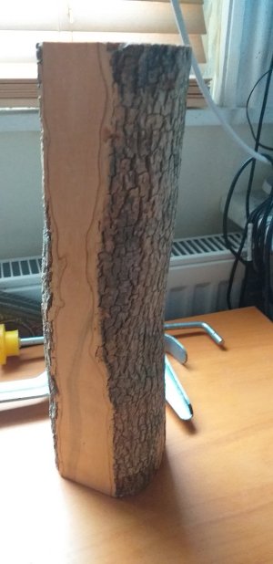
20251029_090228.jpg
 
I did a search on-line for hardwood in England and the returned info is shocking. I am not sure if your hardwood lumber yards are selling wood or platinum. For a first scratch POF, I would use a hardwood species that is easily obtained. Based on what I guess is available I would use Maple (Sycamore - (Acer pseudoplatanus)) or Beech or Birch. I would want to see the grain on the last two. I would never use something as rare and dear as Buxus for framing - the loss to sawdust is just too great. The cost to benefit equation does not support using Buxus for large volume structural elements. For carving and deck structures it cannot be exceeded.
 
Hi Jaager,
You raise a good point. I wouldn't want to disrespect such a rare material. The waste I mention above is largely because of the quality of the colour variation and overall quality of the material.
I'm only considering a 1:96 cross section of Granado based on the plans drawn by Jeff Staudt, so very little material required in total.
The frames will be built from individual futtocks, so minimal waste there. Having said that I did see some cut through logs of the Buxus and they were shot with discolourations, splits and bacterial damage, so there are only quite small usable areas anyway. I can easily obtain very large boards of highly consistent Castello for the floor timbers, lower futtocks, riders and magazine structure, which are the thickest and strongest members.
 
Ditto to what Jaager said regarding the use of boxwood. Boxwood's greatest value is as a carving wood. There are other far less expensive and scarce species which will provide a better appearance if left bright and if they will be painted or stained, there's no difference either way. I'd add swiss pear and cherry to the list of alternate species to consider.

I'd also mention in passing that you may want to do some test runs on building up frames from futtocks at 1:96 scale. That's some very tedious work which quite likely won't even be noticeable without a magnifying glass at that scale if you're using a species without visible grain. 1:96 is 1/8" to the foot so even a six-inch molded frame is 1/16" at scale and on a doubled built-up frame that would make the futtocks 1/32" on their molded dimension. I'm sure you know that, but visualizing it and actually physically doing it, are two different things. It would seem with "as built" framing at 1:96, you are contemplating very difficult miniature scale work for a first scratch-built project. That's McNarry, McCaffery, and Reed level miniature ship modeling!
 
Hi Bob,
I understand your point, but prefer working in small scales. To me 1:96 is medium and 1:72 is large. My current build is 1:160, but that is a bit too small for me in truth. See below.
I'll follow your advice about a test frame. Great idea. It will be a nice break from my current build.
 
I am very grateful to Bob for drawing my attention to potential problems with my proposal. I hadn't really though it through in detail. I especially like his idea of making a test frame to see what I'm getting myself into. It'll keep me away from the Enterprises for a while.

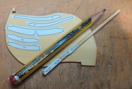
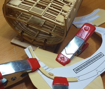
So.....I've prepared a 1:96 Granado frame ready for cutting out when it has dried sufficiently. The trusty fret saw, and the usual files, will be my weapons of choice.

I'm using high-quality Chinese buxus for the frame, and same quality brown Buxus for the chocks in order to create contrast and see the elements more clearly.

I haven't decided whether to make simple isocoles chocks or whether I'll go with the Jeff Staudt's plan and use the stylised chock and scarf method. Hopefully the later.1761823317125.png...........................


20251030_110313.jpg
 
OK, It looks possible. compared to the 1:160 it really is a giant!

looking at the plans, the sweep port sills and fillers will be a real challenge, but with such tiny pieces of wood you can so easily remake if mucked up.

I'll try to complete this single frame tonight and leave it a full 24 hrs to cure and see what we have. Following that I'll reduce the chock and prepare the sides to see whether the required strength is there. To that end I've kept gaps to a minimum, though there is a very slight one between the futtocks. The interior/exterior are already shaped close enough for what little fairing will be required. On the actual model some frames will be doubles, so those will have greater integral strength.

Pretty sure that I'll stick with the stylised chock and scarf method. It really looks nice, though I might save some time by not doing them where the riders hide the chocks. We'll see......................................

20251030_191503.jpg
 
OK, It looks possible. compared to the 1:160 it really is a giant!

looking at the plans, the sweep port sills and fillers will be a real challenge, but with such tiny pieces of wood you can so easily remake if mucked up.

I'll try to complete this single frame tonight and leave it a full 24 hrs to cure and see what we have. Following that I'll reduce the chock and prepare the sides to see whether the required strength is there. To that end I've kept gaps to a minimum, though there is a very slight one between the futtocks. The interior/exterior are already shaped close enough for what little fairing will be required. On the actual model some frames will be doubles, so those will have greater integral strength.

Pretty sure that I'll stick with the stylised chock and scarf method. It really looks nice, though I might save some time by not doing them where the riders hide the chocks. We'll see......................................

Your 1:160 is amazing! I don't know how much of that was prefabbed, but even so, the combings and grates, the beams and carlings, the frames and spacing all look great! I couldn't/wouldn't want to handle detailed frames at 1:96 and, sure, no one is going to appreciate the detail except those who observe here, but it wouldn't be the first time someone built in details to their ship no one was ever going to see.
 
doubled built-up frame that would make the futtocks 1/32" on their molded dimension.
That is exactly what it would be at the top of the top timbers. Delicate to be sure. The floors and futtocks would be thicker, but still delicate if not made as doubled frames as Bob suggests. This will be fun to watch and learn from your experience.
Allan
 
The test was inconclusive. It is possible, but as bob suspected, it's fiddly and not terribly noticable. Also as I have decided to go for a smaller scale, 144 or 160, I'll go with two part frames, grain aligned and maybe a scarf joint.

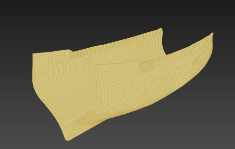
So I've decided to brush off my autodesk CAD and start on the design of the frames for Granado. The rest will be made conventionally.

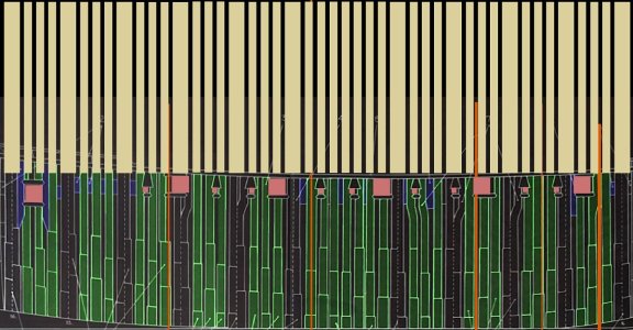
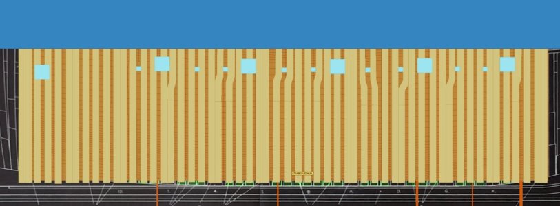
Below is the current extent. Basically the straight frames midship-section. I'm adapting it from plans from Peter Goodwin's book, but they are rather small and the lines alone create inaccuracies.

The long yellow bars are my version of Goodwin's double/single frame arrangment which is seen below them. The flesh coloured rectangles are gun and sweep ports aligned as best as I could for ease of construction. The long orange bars are artifacts from adjusting the original plans which had a wide range of different spacings between station, that I 'corrected?'.

Image5.jpg

Image4.jpg
 
Last edited:
Goodwin has two framing styles:
All bends
Bends at every station and single filling frames between.

You seem to be choosing the more difficult of the two styles.

What I see:
The stations are at 3 bend intervals.
The style with filling frames has more area that is space.

The English had a strange obsession with the location of the floor timbers. Forward of the deadflat "0" the floor is on the forward side of every station. Aft of the deadflat the floor is on the aft side of every station. To be able to do this -- very strange things are done at the deadflat station, Somehow an extra frame has to be added or lost. In Granado it is "lost". 0 station ts two lines. 0aft and 0fore. The distance from 0aft to A is the same as from 0fore to 1. There is a loss of one frame width from 1 to A. Pick 0aft as the 0 station and it is 3 bends from 0 to A and 2.5 bends from 0 to 1.

My research has found that the French and North Americans did not bother with this nonsense - picked a side of a station for the floor and used the pattern for the whole hull.

You do realize that in actual practice that there would have been a slew of chocks between each frame and its neighbor? They probably would not have wasted futtock wood to have the prefect length. There was probably staggering of butt position as seen from the side?

My thesis is that the near universal obsession with perfect symmetry for the line of butts and open spaces all the way is itself a stylized framing. An actual hull would have been irregular and fairly ugly. So, as for which type of stylized framing to use? A joke punchline comes to mind: "We have already determined what you are. Now all we are doing is haggling over the price."
 
I have suggestions:

For framing: split the difference: bend - frame -bend -frame -bend

Do NOT include the deadflat in your section.

If you plank everything above the wale - inside and out - have actual wood where are the spaces. The solid wall is much stronger.
 
The English had a strange obsession with the location of the floor timbers. Forward of the deadflat "0" the floor is on the forward side of every station. Aft of the deadflat the floor is on the aft side of every station.

In my experience, that's pretty much standard operating procedure. The frame faces bevel forward from the widest point on the hull forward and bevel aft from the widest point on the hull aft. The practice minimizes the amount of wood the adze man has to remove when working the bevels on the frame faces. one edge of the frame is always cut to the line. The other edge is beveled from that to create the other edge of the frame face.
 
The station was almost always the location of a bend. The pattern for the station that is the Body Plan is the midline shape for its bend. In English practice wood is adzed FROM the floor. Futtock 1 and cross chock patterns would have been larger and had the bevel adzed TO the station line pattern. But I do not see what difference it makes which timber is where. For about half the hull the cross chock would not be chopped at all.
 
Thank you Jaager and Bob,
This is very helpful.

I am aware of the fact that I have proposed a stylised framing, but it seems easiest to plan and build.

Goodwin illustrates reduced sidings, but they appear randomly in the single frames throughout the hull towards fore and aft, unlike the symmetrical scheme changing direction at the midship in the double frames scema. The futtock thickness and overall spacing is also random (or appears that way to me?). I quite like the idea as it has an organic quality, and I may try to emulate it.
I understand that gunports and sweep spacing were governed by space required by the guncrews etc, so will try to maintain Peter goodwins scheme and see were we land up.
 
Last edited:
The stylized bit was not about you. It was aimed others who make snooty comments about framing that does not mimic the idealized framing occasionally shown in plans of vessels before the 1780's and increasingly common after. I have downloaded about 60 framing plans for RN ships from the 1770's to about 1805. The great majority of them are essentially a solid wall of timbers with 1-2" air spaces. ( It would have been impractical to wait 10 years for a 10" thick balk to completely season.) ( The ships seasoned 'on the hoof' as it were. )

I almost exclusively favor POF. I am not enamored by the look of a solid wall. My response is to mimic the RN shipyard modelers of the late 17thC. and the paintings of open framing of 18thC, Establishment Georgian warships and use a stylized framing with more area as spaces.
The 50% spaces of Hahn/Davis style is too much space for me.

The futtock thickness and overall spacing is also random (or appears that way to me?).
It is not random. There is order to it. There are strict rules - rigid contracts for ships built in private yards.
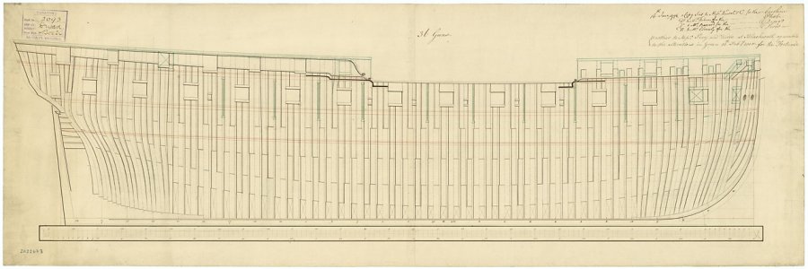
I did a search for Granado 1742 at the RMG site. There are two plans - lines actually. One for Granado alone and one for Granado's class -(Comet +) (The HMS part for the name was only official after the American Revolution. The same as USS was only official after 1900.)

Both are for private yards. The whole class was contracted out. Neither shows any indication of the disposition of the frames.
What Goodwin drew for his AOTS Granado 1742 is probably a best guess and to me the bend- frame-frame-frame-bend disposition looks like something he pulled out of his .... I have not seen that pattern in any other place.

Yep. Just checked again - j0387 = Granado shows a lot of detail but it only shows the sided dimension for one frame - the one at 0.
That allows for an accurate room and space - with two knowns = frame width and station interval - the space is an easy calculation.
By the way "thickness" is the moulded dimension.

I almost forgot -- j7658 - the class - shows the moulded dimension for the midship frame. For most RN ships the mounded dimension can be a bear to determine - the terminology is a bit obscure.

1742 is the Establishment era. I looked up the scantlings in Yedlinsky.
There is a bomb vessel in Steele 1805 a bit later than 1742 but I do not think that the physics and physical properties of wood changed much over that time.
all are sided dimension
Floor 11.5"
F1 11.5"
F2 10.5"
F3 10"
Top at heel 11"
Top at rail 8"

Earlier in the Establishments the closest in size was in 1719 EST.
Floor 11"
F1 10"
F2 9.5"
F3 n.d.
Top heel 10"
Top rail 9"
 
Last edited:
The stylized bit was not about you. It was aimed others who make snooty comments about framing that does not mimic the idealized framing occasionally shown in plans of vessels before the 1780's and increasingly common after. I have downloaded about 60 framing plans for RN ships from the 1770's to about 1805. The great majority of them are essentially a solid wall of timbers with 1-2" air spaces. ( It would have been impractical to wait 10 years for a 10" thick balk to completely season.) ( The ships seasoned 'on the hoof' as it were. )

I almost exclusively favor POF. I am not enamored by the look of a solid wall. My response is to mimic the RN shipyard modelers of the late 17thC. and the paintings of open framing of 18thC, Establishment Georgian warships and use a stylized framing with more area as spaces.
The 50% spaces of Hahn/Davis style is too much space for me.


It is not random. There is order to it. There are strict rules - rigid contracts for ships built in private yards.
I did a search for Granado 1742 at the RMG site. There are two plans - lines actually. One for Granado alone and one for Granado's class -(Comet +) (The HMS part for the name was only official after the American Revolution. The same as USS was only official after 1900.)

Both are for private yards. The whole class was contracted out. Neither shows any indication of the disposition of the frames.
What Goodwin drew for his AOTS Granado 1742 is probably a best guess and to me the bend- frame-frame-frame-bend disposition looks like something he pulled out of his .... I have not seen that pattern in any other place.

Yep. Just checked again - j0387 = Granado shows a lot of detail but it only shows the sided dimension for one frame - the one at 0.
That allows for an accurate room and space - with two knowns = frame width and station interval - the space is an easy calculation.
By the way "thickness" is the moulded dimension.

I almost forgot -- j7658 - the class - shows the moulded dimension for the midship frame. For most RN ships the mounded dimension can be a bear to determine - the terminology is a bit obscure.

1742 is the Establishment era. I looked up the scantlings in Yedlinsky.
There is a bomb vessel in Steele 1805 a bit later than 1742 but I do not think that the physics and physical properties of wood changed much over that time.
all are sided dimension
Floor 11.5"
F1 11.5"
F2 10.5"
F3 10"
Top at heel 11"
Top at rail 8"

Earlier in the Establishments the closest in size was in 1719 EST.
Floor 11"
F1 10"
F2 9.5"
F3 n.d.
Top heel 10"
Top rail
Thanks for that,

I understand some of it but lack deep knowledge of these matters.

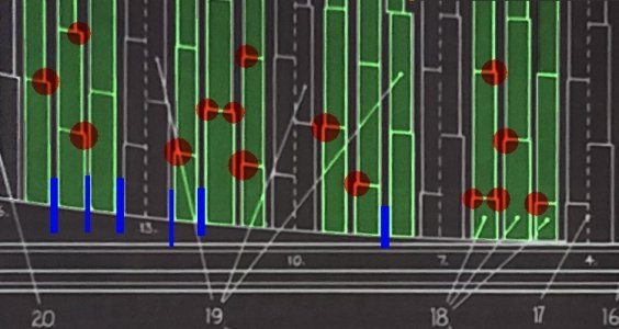
My comment about randomness referred to the Goodwin plans. Below I have highlighted examples of the direction in which the futtocks are narrowed in red, and varying spaces between floor timbers in blue. At the scale that I'll be building at I will not narrowing the siding, (if that is the correct expression), but I would like to vary the distance between floor timbers, if required, to match the Goodwin scheme.

It is my limited understanding that a degree of randomness might be introduced due to material constraints or design and building vagaries?

The bottom image is my current proposal. I agree that the strict verticals are not overly appealing and may try to add floor timbers to break up the monotony lower down, but that could be a challenge at 1:144 or 1:160. There's only one way to find out!................................................

SIDINGS.jpg


current proposal.jpg
 
Last edited:
Of course builders tried to maximize use of “compass timber,” the naturally growing crooked part of the tree, in order to orient the grain for strength. As a natural material, the length of these pieces varied. This would have prevented joints from being lined up in neat rows.

Roger
 
The port on the left and some others cut into the frames to the point that they are of no value to the whole above where they are cut. I just found the drawing below of the bomb vessel Belzebub 1813 that show a few frames but as it is some 70 years later, maybe not a good reference. I could not find any contracts for bomb vessels except the 34 page contract for Belzebub, so again considering the difference in eras, may not be as helpful as hoped for. Note that page 9 is missing. https://www.rmg.co.uk/collections/objects/rmgc-object-388116

Allan

1762798888457.png


The drawing below is not a bomb vessel, but the relation of the ports to the frames can be seen.
1762800123564.jpeg
 
To supplement the above, the English seemed determined to have their timbers frame the gunports and sweep ports without having to cut into them. They were willing to have the tracks of the higher level timbers go around Carter's barn to yield that.

RN: F1 may or may not have been sided less than the floor timber. F2 was usually sided less that F1. F3 was sided less than F2. etc. (I have been unsuccessful in finding a shorthand word to describe this.) Even more fun is at the distant fore and aft regions even the floors could be sided less those amidship.

At your proposed scale, I think that you can have this shrinkage of upper level timber sided dimension done if you threaten the sides of the timbers with a 0000 needle warding file by waving it at them. In other words - too slight a detail to be noticed without magnification. It is probably not worth the effort.
 
Back
Top