• Ships of Scale has incorportated an extra level of security when you log In. Please follow on-screen prompts to acknowledge that you are not a robot via a "Check Box" or a "Pictorial Check Box Puzzle". This is needed due to higher level of AI Activity Security.
  • SUBSCRIBE TO SHIPS IN SCALE TODAY!

    The beloved Ships in Scale Magazine is back and charting a new course for 2026!
    Discover new skills, new techniques, and new inspirations in every issue.

    NOTE THAT OUR NEXT ISSUE WILL BE July/August 2026
  • Win a Free Custom Engraved Brass Coin!!!
    As a way to introduce our brass coins to the community, we will raffle off a free coin during the month of August. Follow link ABOVE for instructions for entering.

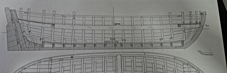
Bateau de Lanvéoc in 1:32 from Ancre Plans by JacquesCousteau

this is sure looking nice!
Thanks! I've really been taking my time with this--my first cut was about 14 months ago. It's been an enjoyable build so far, although the issues I've found with the drawings of the frames (especially the cant frames) have certainly been frustrating at times. Definitely a major step up in complexity from POB models.
 
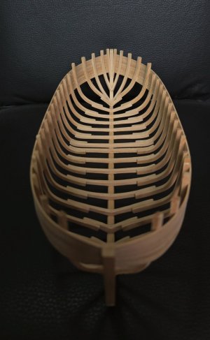
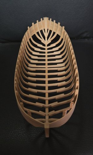
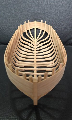
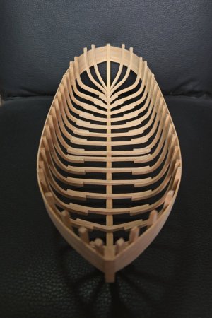
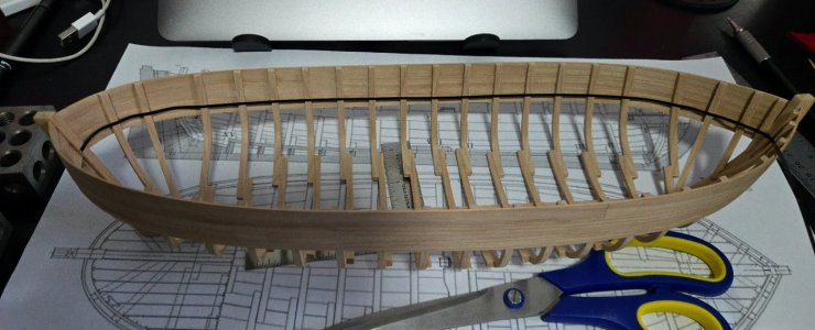
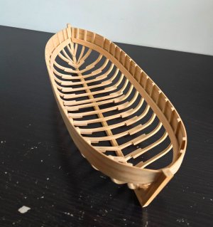
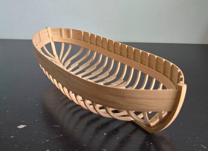
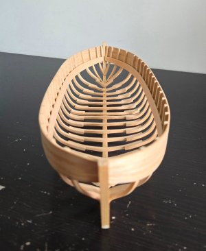
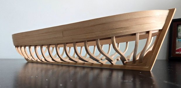
Innumerable sanding sessions later, I'm finally done with fairing the interior! ...on the port side. (Left in the photo below)
20260510_120908.jpg

The frames are supposed to be 2.75mm thick around the top, mine are generally around 2.9-3mm. Close enough for me.

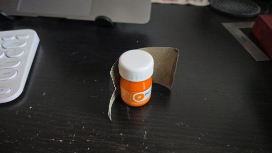
It was really slow progress. Toward the end, I finally went ahead and got some 80 grit sandpaper. I had been worried that it would be too aggressive, but with so much material to remove, it ended up being the right choice. One of my most useful tools was just a strip of sandpaper wrapped around a small paint bottle for getting the curves.
20260510_120637.jpg

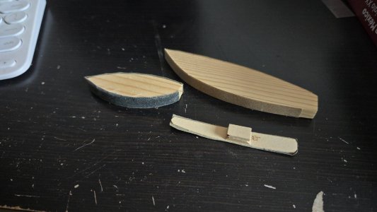
I also used several curved sanding blocks, and a thin flexible sanding strip with a handle, which was especially useful for fairing.
20260510_120700.jpg

The difference between the port side (sanded) and the starboard side (unsanded) is hopefully clear.
20260510_120913.jpg

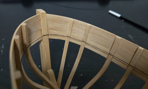
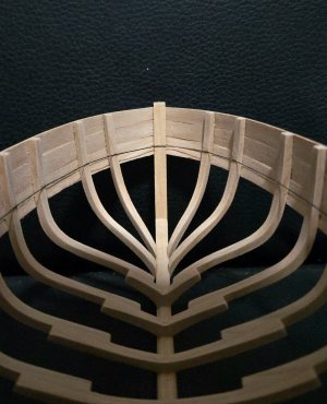
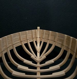
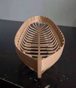
And the view from the bow looking aft:
20260510_120732.jpg

20260510_120829.jpg

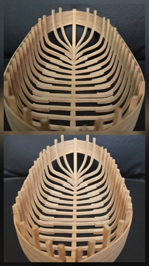
Finally, a collage comparing the inner hull at the start (below) and now (above). It really shows how much I had to remove, especially aft.
20260510_121107.jpg

In the future, I am definitely definitely cutting frames closer to the line. This process is extremely tedious. Hopefully the starboard side is faster with the 80-grit sandpaper.

In other news, I've begun reposting my old disappeared MSW build logs. I began with my scratch-built Spanish fishing boat cross-section, the Juana y José, and have now started on my NRG Half-Hull.
 
Looks really nice!

I agree it is a lot of work, but I'd rather keep a little more extra material to start and fair it down than to cut too close to the line and have a frame that just doesn't fit. 80 grit would be a bit rough for me - I rarely use anything coarser than 120, and more typically 150 and/or 180, even though sometimes it feels like I'm not making any progress.
 
Looks really nice!

I agree it is a lot of work, but I'd rather keep a little more extra material to start and fair it down than to cut too close to the line and have a frame that just doesn't fit. 80 grit would be a bit rough for me - I rarely use anything coarser than 120, and more typically 150 and/or 180, even though sometimes it feels like I'm not making any progress.
That makes a lot of sense. Part of the problem may have been that some of the sandpaper I was using had already been used--I definitely could be better about actually switching to new sandpaper regularly.
 
A very little bit of progress to share.

First, I'm continuing to fair the interior. The starboard side is going a bit faster than the port, it helped to use higher-grit sandpaper and to replace the sandpaper more frequently, and to use the dremel with a sanding tip very very carefully, only for the rough shaping when I still had 2mm or so to remove.

Second, as I mentioned I was planning earlier, I sawed off the remaining timber heads, and used a sanding block to smooth the cuts.
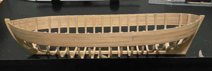
20260524_225537.jpg

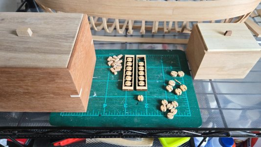
Third, as a break from fairing, I've begun working on the blocks. In future builds, I may try making my own, but I went with a purchased option this time. Way back when I was just starting to plan this build, I bought Syren's block kits, which are no longer manufactured. They're interesting little kits. The blocks themselves are laser-cut, held in a frame, and one side is laser-engraved to hollow out around the sheave. The layers are simply glued up, and the block is then sanded smooth. Below, you can see some assembled, rough-sanded single blocks, and the unassembled double blocks.
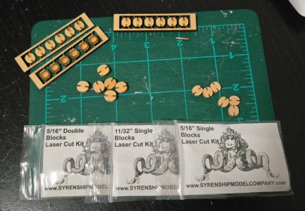
20260524_230007.jpg

I actually had a little bit of trouble with these. On my first batch, I followed the instructions to use super glue applied with a toothpick. Despite clamping to cure, I didn't at all get a good bond, and four of the six blocks came apart either while I was cutting them free of the frame, or when I started sanding, and had to be reglued (some with super glue, some I went with white glue) and carefully lined up. For the second batch, I lightly sanded the lasered side to remove char from the gluing surfaces, and used a larger quantity of glue with the glue brush, applying it much faster than with the toothpick. This worked much better and all the bonds have held up. For the double blocks, I began to do the same, but accidentally misaligned a layer and had to hurriedly slice the blocks apart before the superglue cured fully. After that, I decided to use ordinary white glue instead, so I would have more time to get the alignment right. Below, I'm gluing one layer.
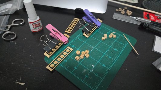
20260524_231732.jpg

Sanding the blocks to smooth them and round off the edges has been more challenging than I expected. They're very small, but large enough that I can't hold them in a hemostat like I usually do to sand small blocks. My fingers got pretty sore holding them. It's easier to use a sanding stick, but still pretty slow going. I tried using a file to roughly shape the blocks while still in the frames, but there really isn't enough space. In the photo below, only a few of the larger single blocks have been final-sanded, the rest are still just rough-shaped. I don't know if these are Boxwood or Alaskan Yellow Cedar (I haven't noticed any odor), but it's a very nice, hard, fine-grained wood. Despite the challenges at the start, they're coming together into quite nice blocks.
20260525_133118.jpg

Unfortunately, I don't think I'll be able to make much progress over the next month or so, besides a bit of sanding here and there. Between a mounting pile of work and deadlines, travel in the second half of June, and a recent medical procedure (which thankfully went well and I'm now recovered), I haven't been able to model much this week and won't be able to for a while. (This is also part of why I've been slow in reposting build logs). Meanwhile, what free time I do have will be mostly taken up making some gifts for family (including the boxes at left and right in the above photo).

 
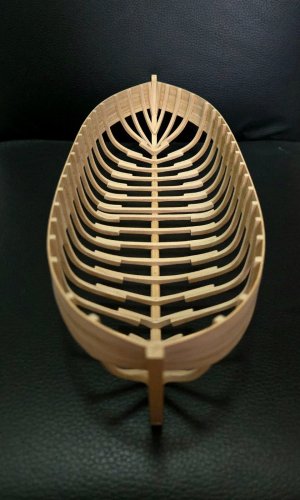
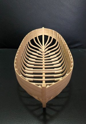
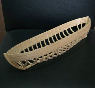
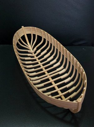
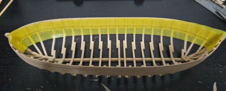
Very brief update, but: I've finally finished fairing the interior! This build has been languishing for a while, but I found the time and motivation this weekend to finally knock out the last sanding. To get into the curves, I found it necessary to round off part of one of my sanding blocks.
20260726_131547.jpg

Then it was just a matter of sanding and checking for fairness with a batten. I also used a vernier digital caliper to measure frame thickness (at least at the top, it was difficult to get it in place to measure lower down). When all was said and done, I did get the frames down to about 2.75mm thick, around where they should be according to the monograph, down from around 6mm thick at the start.
20260727_073424.jpg

20260727_073407.jpg
I learned a really important lesson about being more precise when cutting frames. In the future, while I certainly will still leave room for fairing, I'll also be more careful to cut a bit closer to the lines, and to double check that the lines are actually at the proper thickness as given in the text. In my case, I think that expanding the plans led to some blurryness and imprecision, which was compounded by cutting a bit too wide.
20260727_073353.jpg

20260727_073443.jpg
After fairing, I used a sanding stick to clean the sides and some stringy edges. Next up: working out the location of the clamps.
 
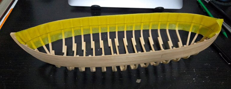
I've had very little time for modeling lately, but did get started on working out the location for the clamps, which run along the interior from bow to stern and support the foredeck, aft deck, and mast support beam. This was a bit tricky. According to the plans, the clamps sweep up a little aft, but it's tricky to tell how much, especially as my wales run slightly differently from the plans.
20260802_173308.jpg

I initially began taking measurements from the plan from the bottom of the keel. However, this was impossible to measure on the model. It would probably be feasible with a very simple build board, with just upright supports fore and aft and the keel resting evenly on a flat surface, but I don't have one and am not going to build one just for this. Instead, I measured down from the sheer line.

To get a smooth run, I tried to mark the upper edge with chart tape. I don't use this for laying out planking belts anymore, but I had some left and figured there would be very little twist to distort the tape. This was incorrect, the tape was unsatisfactory.
20260802_185038.jpg

So, I used thread, instead. This worked perfectly, although it was harder to place it evenly across the interior of the hull--where, if you pull it taught, it tends to pull away from the frames--than it has been across the exterior.
20260802_233524.jpg

I had to adjust the fit down a bit from the measurements at the stern to get something that looked reasonable.

By now I think it's just about there, going to look it over with fresh eyes this weekend before marking it.
20260807_210439.jpg

20260807_210246.jpg

I'm a bit worried about bending the clamps, as they're fairly beefy, about 1/16-inch thick. I'll definitely pre-bend the fore and aft ends before fitting it to the hull.
 
The starboard clamp is on!

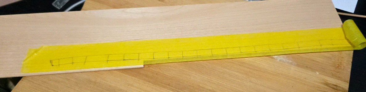
I left the thread in place to make the template, using tamiya masking tape. The plans show the clamp as a single piece extending the entirety of the hull. It's kind of unwieldy to make and fit, so I briefly considered cheating and placing joints under the decking, but decided against it. I suppose it makes sense that an important structural part like this would ideally be one piece, and it's not that big of a boat so it's possible.
20260816_220941.jpg

I also marked each frame on the tape and, after taking it off the model, extended down to get the right plank width.
20260816_223237.jpg

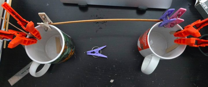
Cutting it out from the 1/16-inch sheet took a lot of passes. It's quite a long piece. As with the planking, I decided to pre-bend the ends before fitting in the hull. The thicker material was a bit slower to curve than the 3/64‐in-thick material I've been using for planking, but it worked. The length just barely fit in my microwave, from the bottom fore corner to the top back corner, in order to be heated after soaking.
20260819_215335.jpg

However, I then realized I'd made a dumb mistake and mixed up the bow and stern ends--the plank had to be bent the other way! I was pleasantly surprised to find that the plank un-bent very easily and took the opposite curve quite well. After another round of pre-bending, I soaked and heat it again and clamped in place.
20260820_142408.jpg

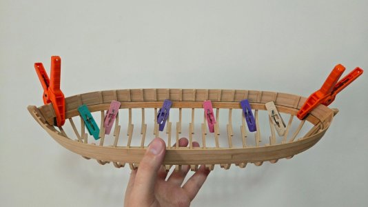
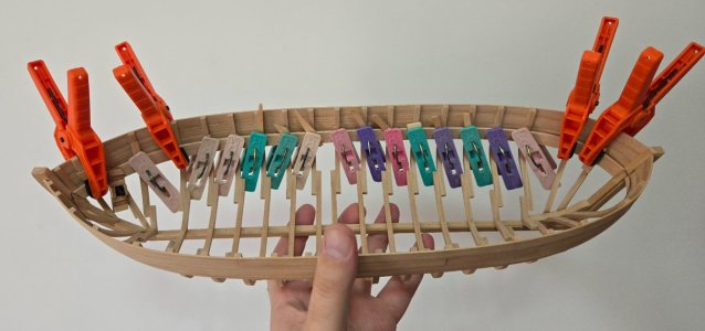
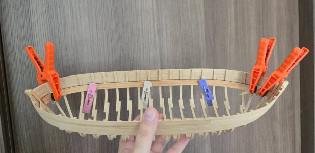
As can be seen, it matched the thread line pretty well, except that it came up ever so slightly at the bow. So, after it dried, I slightly trimmed back the fore top side. Actually gluing the part in place took a lot of clamps. Doing a load of laundry at the same time made me realize that we really need more clothespins...
20260821_105823.jpg

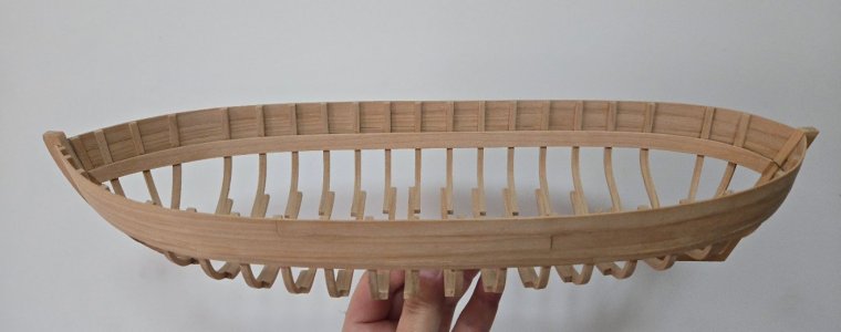
And finally, the starboard clamp is in place. The port one should be the same procedure, I'll just need to be extra careful to get it lined up right to match the height.
20260822_084633.jpg

Work has been pretty overwhelming lately, with way too many nights (including some weekends) working to midnight or later over the past six weeks or so. It's been nice to have a bit of a breather for a couple days. Next week will be hectic again, but after that, I should finally be back on a more normal work schedule, with more regular time for modeling. I'm looking forward to it. I feel like my builds have really stalled out over the past few months, and I'd love to have some more workshop time and finish at least one of these models, as I'm itching to start a new one.
 
Hi,
You could ask the company "Kolderstok", what it would cost for sending such an item to Mexico, perhaps he can make a deal on it, but on the other hand I do not want to disturb your "meditative" feelings, of course, planking your awesome models :)
By the way, I admire your skills building such scratch models, something I am not able off !!

 
Thanks, you may be surprised by what you can do if you try scratch-building (starting from something simple, workshop/tool/material access permitting).

The port clamp followed the exact same procedure, except I didn't bend the plank the wrong way this time.
20260822_202010(1).jpg
20260823_094918(1).jpg
20260823_160350(1).jpg

With that, both clamps are in! The hull is exceptionally sturdy.
20260825_113634(1).jpg
20260825_113718(1).jpg
20260825_113738(1).jpg
20260825_113752(1).jpg

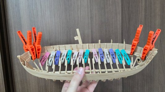
However, a problem: the pressures of the clamps have induced a bit of hogging to the hull, visible below the keel in the following photo:
20260825_113940(1).jpg

This is a bit frustrating and I'm not really sure how it could be avoided--I already pre-bent the clamps before gluing to minimize pressures. I guess I would have had to clamp the keel firmly to a flat rigid surface during gluing, which would have impeded clamping during gluing. I think I can live with it if necessary, but for now, I'm trying to minimize it. First, I've moistened the clamps, weighed down the interior with 3-2-1 blocks, slightly propped up the bow and stern, and used scrap wood to lightly prop apart the middle sides. Second, when I get to the keelson, I'll make sure to have the keel clamped to a flat surface while gluing. (That said, before I can add the keelson I need to drill the holes for the stand, which will need the display base ready, so there are a few steps until then).
 
This project has been a bit on the backburner lately. Partly because I'm trying to finish my Muscongus Bay Sloop model, but also because the next step required getting into the carpentry workshop, which I haven't been able to do lately.

Although I could be working on the gunwales, I'd really like to add the keelson, which I made quite a while ago. However, before I do it, I need to drill holes in the keel for the stand. (My plan is to use brass tubing, with holes all the way through the keel and a small stop blocks added above, which will be covered by the keelson.) I've had trouble getting these lined up, so I wanted to drill the holes in the base at the same time using the holes in the keel as a guide. So, before I add the keelson, I need the base.

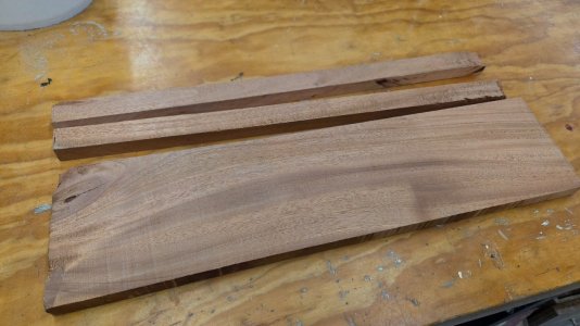
I got some nice mahogany from a lumberyard in Veracruz that I wanted to use for the base, as well as for an unrelated picture frame. But, after cutting off the strips for the frame, I found that the board was a bit warped, undoubtedly from the humidity changes between humid Veracruz and dry Mexico City.
20260820_174157(1).jpg

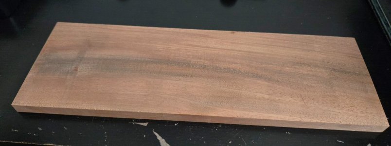
After trimming the board to length, cutting off the knot and splitting at left above, I began work on flattening the board. I started with a hand plane to take down the high corners, then ran it through an electric planer. I had a lot of problems with tearout, although I went very slowly with the planer, taking an hour to shave off a very little at a time, usually running it through a dozen times per side before adjusting by a hair.
20260920_100749(1).jpg

The final result still needs some sanding and scraping, as well as shaping at the edge. I have an interesting old molding plane I'd like to try, but it still needs work to get it working properly, so I think I'll probably just plane a chamfer on the edges.

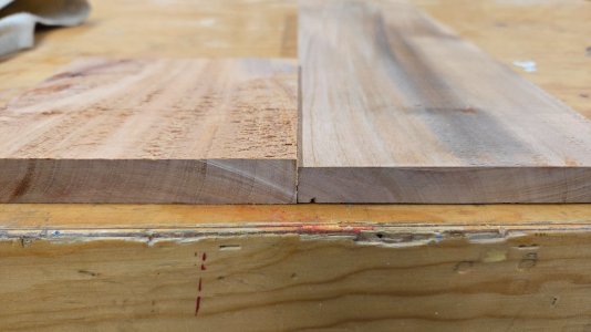
As can be seen, I ended up taking off a lot in my unsuccessful quest to not have so much tearout. (Original at left, planed at right.)
20260919_171018(1).jpg

Learning to mill my own wood is a useful skill for scratch-building, especially as thin sheets and the like aren't readily available here, but wow it takes a lot of time and effort. I may just keep buying pre-milled stuff on my visits to the US for the time being, I'd rather spend my limited hobby time actually building stuff instead of flattening boards.
 
Back
Top