
• SUBSCRIBE TO SHIPS IN SCALE TODAY!

    The beloved Ships in Scale Magazine is back and charting a new course for 2026!
    Discover new skills, new techniques, and new inspirations in every issue.

    NOTE THAT OUR NEXT ISSUE WILL BE MARCH/APRIL 2026
  • Win a Free Custom Engraved Brass Coin!!!
    As a way to introduce our brass coins to the community, we will raffle off a free coin during the month of August. Follow link ABOVE for instructions for entering.

The Hayling Hoy, 1759 by AnobiumPunctatum - scale 1/36

Joined
Oct 23, 2018
Messages
932
Points
403

There were two really good build logs for this model on MSW 2.0 that were a big help to me at the start of my project. That’s why I haven’t planned on writing my own build log - I simply had too many build logs that I’d started but not finished until now. Since both of those old logs are no longer available following the relaunch of MSW, I’ve changed my mind.

A few years ago I bought the really nice book "The Hayling Hoy of 1759-1760" by David Antscherl, published by SeaWatchBooks LLC. It was a nice addition to the other books from the same author I collected over the years and I have never planned a model of this small harbor vessel. I was busy with my sloop Fly.

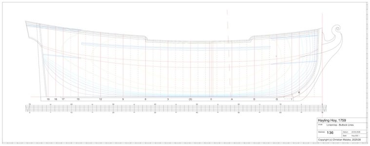
Due to my job, I spent several months last year staying at a hotel in the Netherlands during the week. Since evenings at the hotel can drag on, I was looking for something meaningful to do. That’s when my eye fell on the monograph on the shelf, and I decided to reconstruct the line drawings—which were missing from the book—using the original plans.

Last fall, my father (who will turn 90 next year) asked about the progress on my Fly. He was visibly disappointed that I had to put the project on hold because of my job.

From that conversation came the idea to tackle a small model that could be managed with the free time I have available and hopefully be completed by his 90th birthday. In the meantime, I’ll keep him updated on the progress. The Hoy seemed to me to be an excellent model for the model-building project
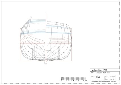
 

The reconstruction of the line drawings:​

The RMG archives contain four drawings of the Hayling Hoy:

  • ZAZ5827 – an initial design of the ship dated August 3, 1759
  • ZAZ5828 – Lines and Profile, the final design dated August 30, 1759
  • ZAZ5829 – Lines and Profile, a copy of ZAZ5828 from September 1759
  • ZAZ5830 – Lines and Profile; according to the RMG website, this is the shipyard plan from the Portsmouth Dockyards
Comparing the various plans reveals several minor differences. For my reconstruction, I used the shipyard plan ZAZ5830 as a basis.

Body Lines.jpeg Buttock Lines.jpg
 

Additional Drawings:​

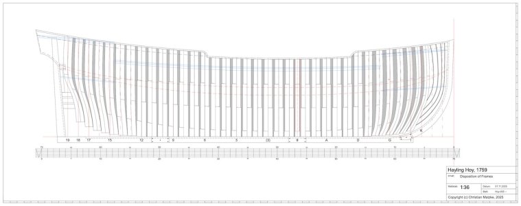
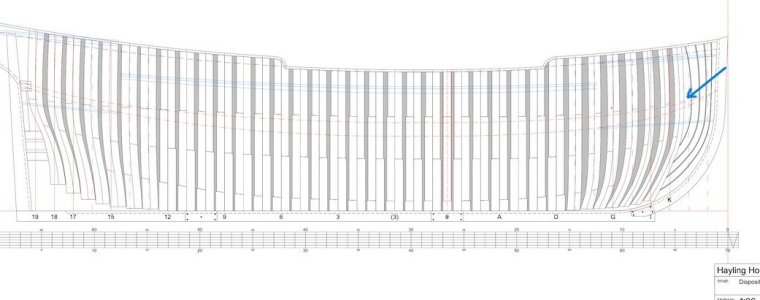
After completing the line drawings, I created a longitudinal section and the Disposition of Frames plan. All dimensions and information are based on the data provided by David Antscherl and the plans included in the book. I made some small adjustments which will help me during my build. I then drew out the frames and created the first milling templates for my CNC machine.

Of course, as the two build reports on MSW have shown, you can also build your model using only the plans from the book. However, since I enjoy creating the drawings, prefer a different scale, and need a digital template for my CNC, this seemed like the easiest approach to me.

Disposition of Frames.jpg

If you compare the transition between the keel and the lower apron with the layout on the Fly, you can see that David has mirrored it. I chose the same layout as on the Fly. I consider the representation in the original plan to be a simplification, one that I’ve also seen in other plans.
 

The build board​

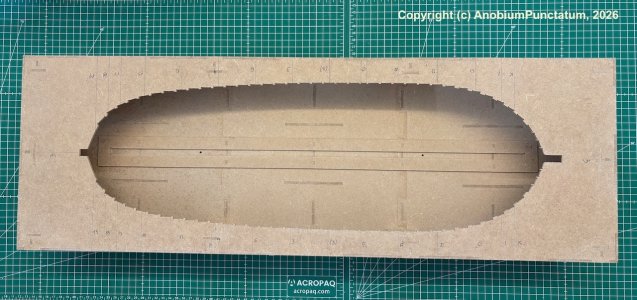
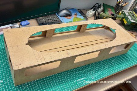
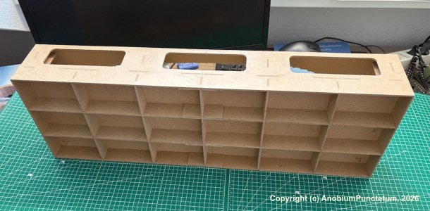
Since I had issues with symmetry in my other projects, I decided to build a small build board modeled after those used by French model builders.

For this, I created milling templates based on my drawings, which I then milled using my CNC machine. The slipway is made of 3mm MDF and is extremely sturdy once assembled. In the future, I would use 5mm MDF for the deck board and not mill through the grooves.

Hoy-001.jpeg

Hoy-002.jpeg

Hoy-003.jpeg
 

The keel​

I chose boxwood and holly as the materials for building the model.

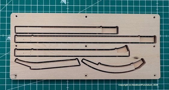
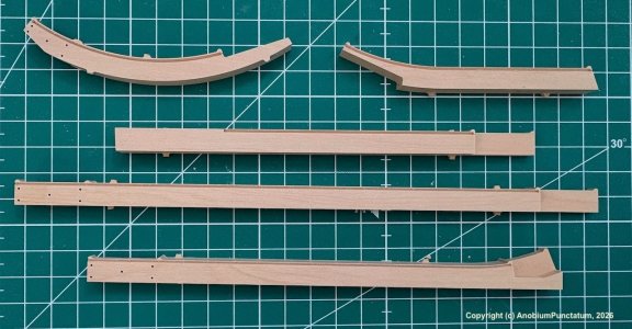
The keel-laying ceremony for my model took place in mid-January of this year. The components, which I had designed in CAD, were milled on my CNC machine. The rounded corners of the board are part of the setup required for milling on both sides. The small thickened sections at the ends of the components are necessary to prevent the wood from splitting after the rabbet is milled.

Hoy-004.jpeg

Hoy-005.jpeg

To ensure that the Fore Deadwood, After Deadwood and Rising Wood are glued in place as centered as possible later on, I milled a few small recesses into which small, matching dowels will be glued during assembly. You can also see the nuts that will be used to screw the finished model onto its stand.

Hoy-006.jpeg

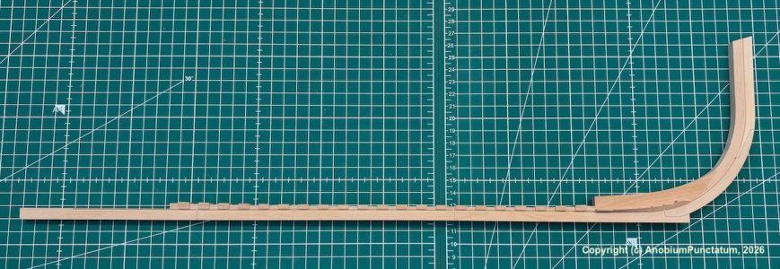
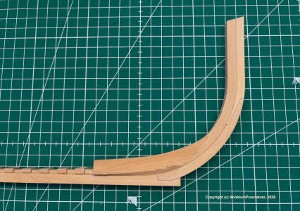
The last two photos show the assembled keel with the stem, fore deadwood, and rising wood.

As you can see in the close-up, I haven’t fully sanded the deadwood yet. To prevent splintering of this extremely delicate component, I’ll make these adjustments only after all the frames have been glued in place. For the wooden dowels, I used 0.80 mm boxwood, which I rounded off with a rounding tool. The dowels themselves were driven into 0.8 mm holes using a small hammer. No glue was required. In the photo, the dowels are barely visible. This will change once the finished model has been treated with oil.

Hoy-007.jpeg

Hoy-008.jpeg
 

The After Deadwood​

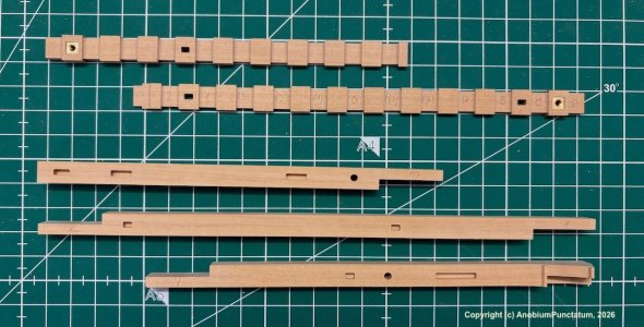
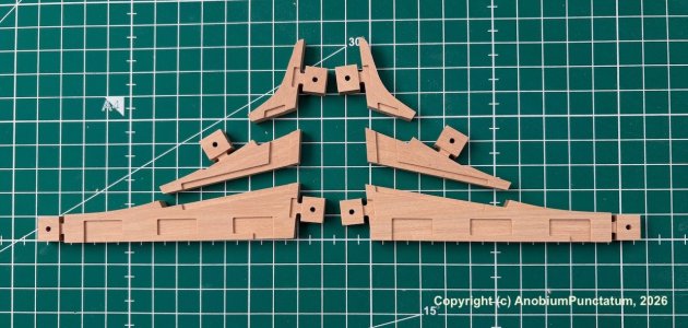
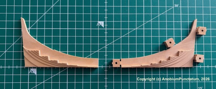
It’s no exaggeration to call the stern deadwood my biggest challenge when building a keel. Even with my CNC machine, I spent a long time searching and sacrificed several small boards before I found the solution I’d like to share with you now. Unlike on the full-scale ship, I cut the deadwood lengthwise. This allows me to perform all the milling operations on the flat surface of the piece. This little trick is also virtually invisible on the finished model, since the keelson covers the glue joint.

First, the deadwood components are cut out. In the photo, you can see the recesses milled on the back for the fitting pieces, which allow the finished halves of the component to be glued together precisely. The small squares with the holes are used to secure the glued-together components to the CNC’s sacrificial plate.

Hoy-009.jpeg

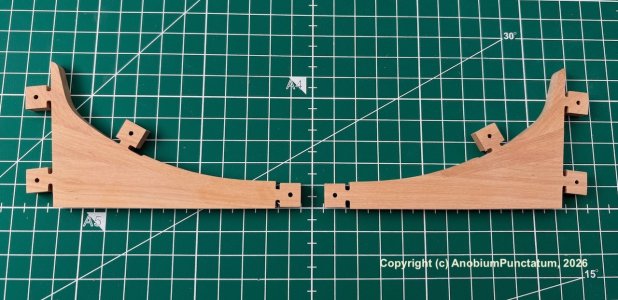
Next, I glued the parts together. It is important to make sure that the side with the cutouts is facing down to ensure a truly flat bonding surface.

Hoy-010.jpeg

In the next step, the prepared halves are screwed to the CNC table, and all necessary milling operations are performed. Given the large scale of my project, I find it very helpful to mill the steps that hint at the future shape of the deadwood. In the following photo, the retaining tabs on the starboard side have already been sawed off and sanded down.

Hoy-011.jpeg

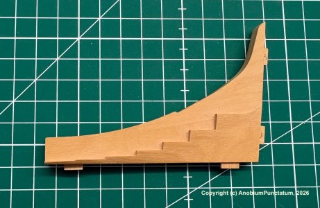
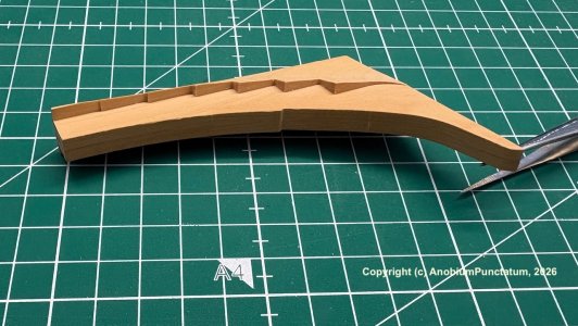
The last two pictures show the finished component. However, it will still be a while before I can glue the deadwood to the keel. I find it much easier to adjust the frame recesses without the stern.

Hoy-012.jpeg

Hoy-013.jpeg
 
Very cool project! I'm looking forward to following along, the CNC work looks fantastic. I ordered the monograph recently (although I haven't read it, it's being held by my family in the US until I visit them), and am considering either a full build or a cross-section model in the near future.
 
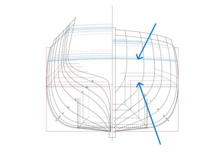
Hi! I'm delighted by your choice and extremely excited about a new, hightly competent Hoy project. I'm noticing you did not follow Antscherl's monograph for your own frontmost cant frame and, consequently, for the hawse pieces design. While the practicum suggests a streight "U" pattern, all available ZAZs show a tumblehome for that. Con is the akwardness of hawse pieces for sure, the aftermost above all. I struggled a lot with the two inlays required to fill the lanceolate gap between the 2nd hawse piece and the frontmost cant frame. Good luck with your project. The start, as usual with your shipyards, is pretty amazing!

Disposition of Frames 2.jpg

Body Lines 2.jpeg
 
Very nice. Go Christian, go! I will follow :-)
You are really welcome Dirk

Hallo Christian, you can literally feel how your past experiences are already shaping the fabrication details of this model. Brilliant!
It's alway a long way to go. Thanks for the nice compliment.

You do the most beautiful workmanship Cristian. Well done so far.
Thank you very much, Bryan

Very cool project! I'm looking forward to following along, the CNC work looks fantastic. I ordered the monograph recently (although I haven't read it, it's being held by my family in the US until I visit them), and am considering either a full build or a cross-section model in the near future.
I would not go for a cross section. There is not much interesting to show in a midship section

It is nice to read that you have found a great way to spend your free time in the hotels, Christian.
An interesting execution of the plans and generating the data for your CNC in this way. The parts look well-made and the assembly seems to be progressing smoothly. Your father will be pleased!
Regards, Peter
I'm really happy that the lot of work I've put in is finally paying off

Good to see you are still active in woodbuilding, Christian! Thumbsup
Thank you very much Ronald
 
Hi! I'm delighted by your choice and extremely excited about a new, hightly competent Hoy project. I'm noticing you did not follow Antscherl's monograph for your own frontmost cant frame and, consequently, for the hawse pieces design. While the practicum suggests a streight "U" pattern, all available ZAZs show a tumblehome for that. Con is the akwardness of hawse pieces for sure, the aftermost above all. I struggled a lot with the two inlays required to fill the lanceolate gap between the 2nd hawse piece and the frontmost cant frame. Good luck with your project. The start, as usual with your shipyards, is pretty amazing!

View attachment 607146

View attachment 607147

There is only one filling piece required. There is a double cant frame followed by the filling piece.
I found no other solution with the given information from the original drawings. Every time I tried to change the design in the direction from David, the horizontal and / of vertical lines are not smooth. Perhaps this is something you can change manually but not with an CAD design.
 
Back
Top