• SUBSCRIBE TO SHIPS IN SCALE TODAY!

    The beloved Ships in Scale Magazine is back and charting a new course for 2026!
    Discover new skills, new techniques, and new inspirations in every issue.

    NOTE THAT OUR NEXT ISSUE WILL BE MARCH/APRIL 2026
  • Win a Free Custom Engraved Brass Coin!!!
    As a way to introduce our brass coins to the community, we will raffle off a free coin during the month of August. Follow link ABOVE for instructions for entering.

The Hayling Hoy, 1759 by AnobiumPunctatum - scale 1/36

Dear Christian
A very impressive start to a beautiful project!!!
I will continue to follow the project with great interest and curiosity.
I would be happy if you would elaborate on the way and methods of working with the cnc, so that we can learn from your most impressive abilities!
 
Dear Christian
A very impressive start to a beautiful project!!!
I will continue to follow the project with great interest and curiosity.
I would be happy if you would elaborate on the way and methods of working with the cnc, so that we can learn from your most impressive abilities!

Thank you very much. As I haven't planned to write a build in the beginning of the project. I have not much much fotos, to show the preparation of the different parts. Sorry, for a more detailed description you have to wait until I continue with the Fly.
 
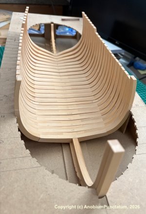
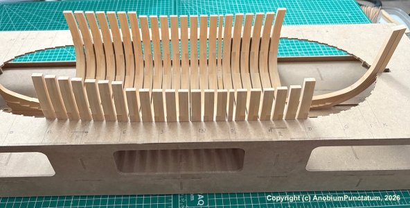
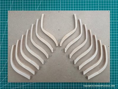
In mid-February, I began building the parallel frames. As shown on the Disposition of Frames plan, the parallel frames consists of 21 double frames and one single frame (midship frame).
To compensate for any inaccuracies during assembly, I added 2/10 mm to the inner and outer sides for the frame thickness when preparing the individual parts for my CNC machine. Only time will tell whether this allowance is sufficient or if I will need to add another 1/ to 2/10 mm in the future for my next project.
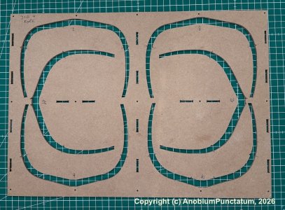
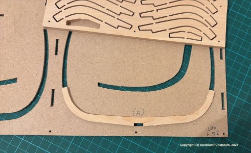
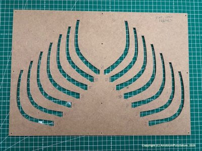
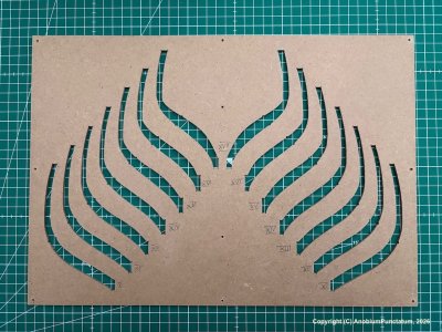
Due to the tight tolerances, I milled a small jig for each double frame. This allows the components to be assembled very precisely and quickly.

Hoy-014.jpeg

Hoy-015.jpeg

Originally, I had planned to use a two-part template; however, this idea didn't work out as intended. So I decided right away not to use the upper part of the template after the second frame.

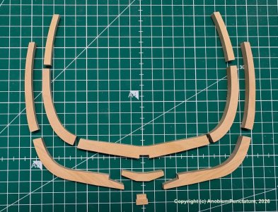
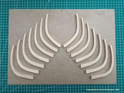
One half of the frames consists of floor timber (10'‘), second futtock (9’'), and toptimber (8'‘), while the other half consists of a crosschock (9.5’'), first futtock (9.5'‘), and second futtock (8.5’').

Hoy-016.jpeg

First, I assemble the half consisting of the first and second futtocks in the template.
Hoy-017.jpeg

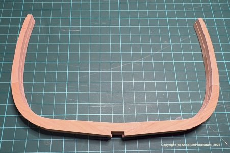
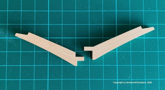
Then I glue small spacers onto the second futtock to compensate for the 7/10mm offset. Now I flip the component over and place it back into the template. Now the other half is glued onto the first half. The small part shown in the photo with the individual frame members is very helpful for aligning the floor timbers.

Hoy-018.jpeg

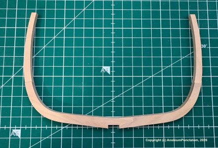
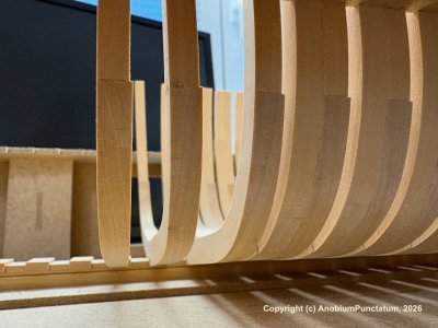
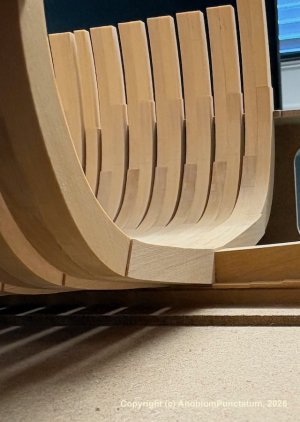
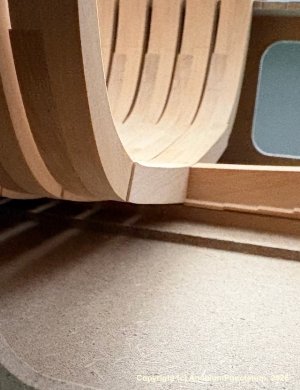
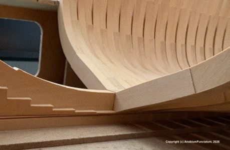
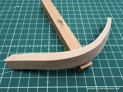
I assembled the floor timbers for frames 10–12 from two separate pieces. This way, the grain of the wood aligns better with the direction of the frames. David Antscherl described this technique in his book "The Fully Framed Model", Volume I. You can’t see this on the finished model.

Hoy-019.jpeg
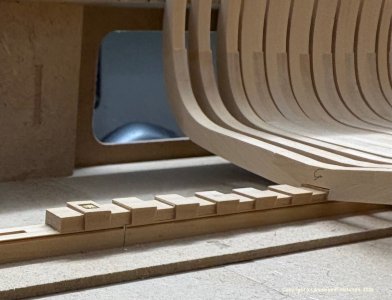
(The photo is from my Alert project)
 
In mid-February, I began building the parallel frames. As shown on the Disposition of Frames plan, the parallel frames consists of 21 double frames and one single frame (midship frame).
To compensate for any inaccuracies during assembly, I added 2/10 mm to the inner and outer sides for the frame thickness when preparing the individual parts for my CNC machine. Only time will tell whether this allowance is sufficient or if I will need to add another 1/ to 2/10 mm in the future for my next project.
Due to the tight tolerances, I milled a small jig for each double frame. This allows the components to be assembled very precisely and quickly.

View attachment 608120

View attachment 608121

Originally, I had planned to use a two-part template; however, this idea didn't work out as intended. So I decided right away not to use the upper part of the template after the second frame.

One half of the frames consists of floor timber (10'‘), second futtock (9’'), and toptimber (8'‘), while the other half consists of a crosschock (9.5’'), first futtock (9.5'‘), and second futtock (8.5’').

View attachment 608122

First, I assemble the half consisting of the first and second futtocks in the template.
View attachment 608123

Then I glue small spacers onto the second futtock to compensate for the 7/10mm offset. Now I flip the component over and place it back into the template. Now the other half is glued onto the first half. The small part shown in the photo with the individual frame members is very helpful for aligning the floor timbers.

View attachment 608124

I assembled the floor timbers for frames 10–12 from two separate pieces. This way, the grain of the wood aligns better with the direction of the frames. David Antscherl described this technique in his book "The Fully Framed Model", Volume I. You can’t see this on the finished model.

View attachment 608125
(The photo is from my Alert project)

That is looking very nice, Christian.
Regards, Peter
 
Back
Top