
-

SUBSCRIBE TO SHIPS IN SCALE TODAY!
The beloved Ships in Scale Magazine is back and charting a new course for 2026!
Discover new skills, new techniques, and new inspirations in every issue.
NOTE THAT OUR NEXT ISSUE WILL BE July/August 2026 -

Win a Free Custom Engraved Brass Coin!!!
As a way to introduce our brass coins to the community, we will raffle off a free coin during the month of August. Follow link ABOVE for instructions for entering.


You are using an out of date browser. It may not display this or other websites correctly.
You should upgrade or use an alternative browser.
You should upgrade or use an alternative browser.
USS Constitution by BlueJacket 1:96
- Thread starter g8rfan99
- Start date
- Watchers 22
-
- Tags
- bluejacket constitution



I just sent him a bunch.I'm sure Jon will chime in with the appropriate photos
Jon
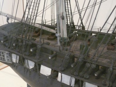
Indeed he did...a bunch. Thanks again Jon. I focused mainly on the ones of the Hull model. We all know that there are some discrepancies and some missing items on this model, which have been attributed to the builders having to hurry up toward the end. Despite there being some missing items, I have always felt that the items that were present on the model must surely have been on the actual ship. With that in mind, the photo below clearly shows that the large cleat directly opposite the Mizzen mast is present
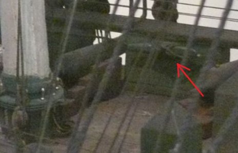
Although not nearly as clear, it also appears that there is one just before the transom
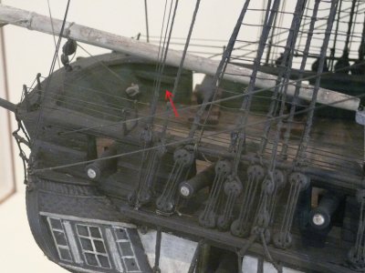
I wasn't really expecting the one at the rear of the ship. There are no cleats either fore or aft of the waist as there is today. Then there is the bow. Although the angles in the photos were not the best, I couldn't really see any evidence of any cleats at all, large or small. Now perhaps the smaller ones were too small a detail to include, as they were rushing to finish, but I would have expected the larger one to be there. I'm inclined to put all of these there, even though they are not on the Hull model. Lastly, regarding the bow. The BJ kit indicates that there is a curved pin rail going across the front of the bow, whereas the Revell kit indicates that there are two pin rails on either side of the bowsprit. Unfortunately, the Hull model does not have any pin rails at all on the entire ship. I suppose since the model was made without sails, they felt this was something they could leave off. What the model does show pretty clearly to me is that the arrangement of the step leading to the bowsprit and the small fo'c'sle that the hammock netting tied into would get in the way of the pin rail if it were going all the way across the bow. So, I think I will go with the pin rails as shown in the Revell model.
Right or wrong, that's the way I'm going to do it. In the words of Collin Raye "that's my story, and I'm stickin' to it"
Although not nearly as clear, it also appears that there is one just before the transom
I wasn't really expecting the one at the rear of the ship. There are no cleats either fore or aft of the waist as there is today. Then there is the bow. Although the angles in the photos were not the best, I couldn't really see any evidence of any cleats at all, large or small. Now perhaps the smaller ones were too small a detail to include, as they were rushing to finish, but I would have expected the larger one to be there. I'm inclined to put all of these there, even though they are not on the Hull model. Lastly, regarding the bow. The BJ kit indicates that there is a curved pin rail going across the front of the bow, whereas the Revell kit indicates that there are two pin rails on either side of the bowsprit. Unfortunately, the Hull model does not have any pin rails at all on the entire ship. I suppose since the model was made without sails, they felt this was something they could leave off. What the model does show pretty clearly to me is that the arrangement of the step leading to the bowsprit and the small fo'c'sle that the hammock netting tied into would get in the way of the pin rail if it were going all the way across the bow. So, I think I will go with the pin rails as shown in the Revell model.
Right or wrong, that's the way I'm going to do it. In the words of Collin Raye "that's my story, and I'm stickin' to it"

This Hull model is new to me. Where online (?) Would I find access to it - for future reference?
I originally found the 1812 Isaac Hull Model at the Peabody Essex Museum on the Fine Scale Modeler site. Then I supplemented the collection as I found various images on other sites. (I have a total of 75 images) When I checked the original link to Fine Scale Modeler, all the text was there but the images were not, just placeholders. The text does have a link to an excerpt from Constitution All Sails Up and Flying by Olof A. Eriksen which gives a history of the model. If you have a copy of that book, the text begins on page xxii.
Jon
Jon
I just looked it up on the internet. One copy is supposedly available through Amazon at about $142. Delivery though is not until mid-august, which has me scratching my head. Nothing available at eBay, or any other website I've checked. Is this book worth the expense? And the wait?
While trying to locate my original source of Hull pictures, I ran across this forum post by Marcus.K, May 2007 on Fine Scale Modeler which discusses the historical colors and configurations of the Constitution. It's worth a look if you want a realistic 1812 model.
Jon
Jon
I believe it is an awesome book with a great deal of detailed information, but the cost has always been the road block for me. It does come up on ebay once and a while. You might also try Thrift Books, they sometimes get a copy
As for the Hull model, I first found out about it on the museum website. You would think there would be a lot more images available for it, but I've looked without a lot of success. Jon is probably the best source
As for the Hull model, I first found out about it on the museum website. You would think there would be a lot more images available for it, but I've looked without a lot of success. Jon is probably the best source
I'm less concerned about realism in my own model, just trying to decide whether or not to add to my library in case I do this again from scratch. Better to have it and not use it than need it and not have it. If you're telling me the book is worth having on its own Merit..
Peter, this is a great book for detailed rigging and sails. It's value to you depends on how accurate you want to rig your model. BTW, did you check to see if it was available as an eBook? The printed version I have is a soft cover 8.5" x 11" in size.
Jon
Jon
All I could find was the paperback version. If the details are that good, and applicable to rigging, the more information I have on that, since I'm going to threshold of actually starting rigging, the more I'm inclined to make the investment. I can afford a few extra dollars, I'm put off by the wait until August 16th to receive it.
Peter, from everything I've seen and heard about this book, you'll be very happy with the purchase and find it worth the wait. I would love to buy this book myself, but my wife would have a conniption if I spent more than $100 on a book. Besides, I'm still holding out hoping that you decide to get rid of that mill .
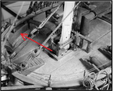
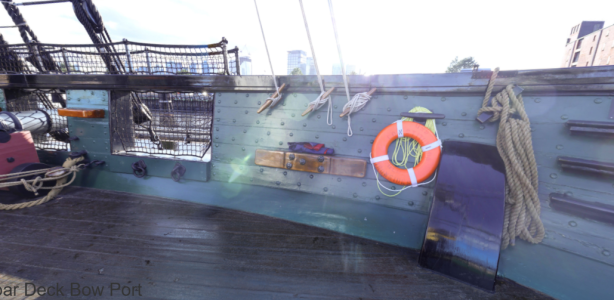
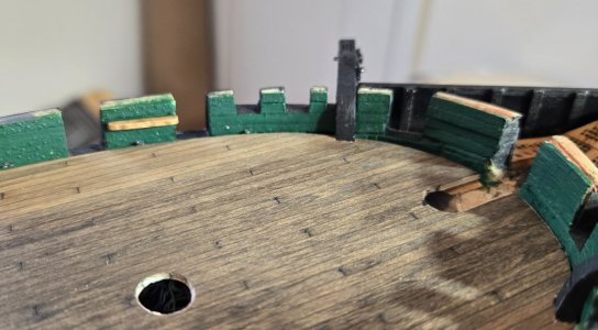
I thought I would get started on the cleats this morning and very quickly realized why the Hull model does not show any up near the bow. Bottom line, there is nowhere to put them. The bulwark design at the bow was different then. From the last gun port to the catheads, the upper half of the bulwarks were open as you can see in the photos here
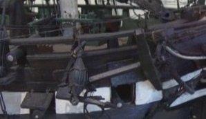
This is exactly where those cleats need to be
Early on in the build, I had decided to construct the bulwarks in this open manner, similar to the Hull model (and the Revell kit)
So, although I could put the large cleat there if I wanted to, there is no where to put the smaller cleats. I'm not sure what the larger one is intended for, but the smaller cleats appear to be used for running rigging, which I'm not going to have since I have pretty much decided against sails. So, no cleats at the bow, just the two large ones at the aft end of the ship. It's a shame I went to all the trouble to make those really nice looking cleats that will never get used.
.I thought I would get started on the cleats this morning and very quickly realized why the Hull model does not show any up near the bow. Bottom line, there is nowhere to put them. The bulwark design at the bow was different then. From the last gun port to the catheads, the upper half of the bulwarks were open as you can see in the photos here
This is exactly where those cleats need to be
Early on in the build, I had decided to construct the bulwarks in this open manner, similar to the Hull model (and the Revell kit)
So, although I could put the large cleat there if I wanted to, there is no where to put the smaller cleats. I'm not sure what the larger one is intended for, but the smaller cleats appear to be used for running rigging, which I'm not going to have since I have pretty much decided against sails. So, no cleats at the bow, just the two large ones at the aft end of the ship. It's a shame I went to all the trouble to make those really nice looking cleats that will never get used.
I installed the cleats near the transom and also under the sheave up by the Mizzen mast. I also installed the steps on the transom, which in this period were in the corners not the middle as they are today, and the small iron cleat for the gaff vangs
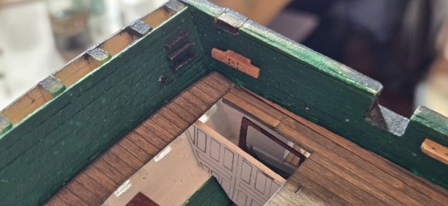
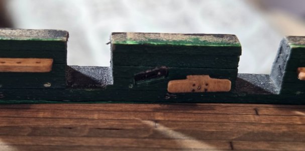
I had thought there was going to be alot more to do to the bulwarks, but apparently for my time period, that's about it. So, it was time to get ready for all the carronades, starting with the eyebolts. As I have mentioned before, I use fish hooks for my bolts. Just cut the eye off using the appropriately sized hooks. Although I don't plan on installing the inhaul tackle, I went ahead and put these eyebolts in place. I drilled the holes for the breech line ring bolts, but these wont be installed now. It is much easier to attach and seize the breech line to the ring bolts and then put them into the bulwarks when the gun is glued to the deck. The last to be done is the double eyebolts for the training tackle. These I made by hand using 28 ga. wire. I tried using Mustafa's method of making two loops at each end of a piece of wire and then folding it in half, but with this tiny wire, I found it more difficult than my original way of looping it around two closely spaced pins
I installed the cleats near the transom and also under the sheave up by the Mizzen mast. I also installed the steps on the transom, which in this period were in the corners not the middle as they are today, and the small iron cleat for the gaff vangs
I had thought there was going to be alot more to do to the bulwarks, but apparently for my time period, that's about it. So, it was time to get ready for all the carronades, starting with the eyebolts. As I have mentioned before, I use fish hooks for my bolts. Just cut the eye off using the appropriately sized hooks. Although I don't plan on installing the inhaul tackle, I went ahead and put these eyebolts in place. I drilled the holes for the breech line ring bolts, but these wont be installed now. It is much easier to attach and seize the breech line to the ring bolts and then put them into the bulwarks when the gun is glued to the deck. The last to be done is the double eyebolts for the training tackle. These I made by hand using 28 ga. wire. I tried using Mustafa's method of making two loops at each end of a piece of wire and then folding it in half, but with this tiny wire, I found it more difficult than my original way of looping it around two closely spaced pins
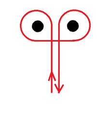
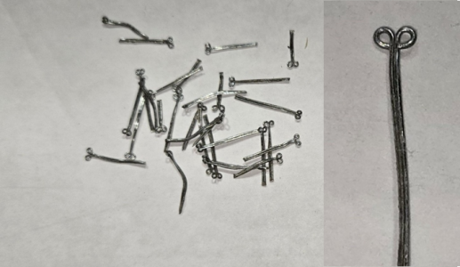
After cutting to size, I heated them up with a torch until red hot, which blackened them
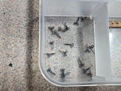
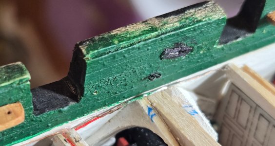
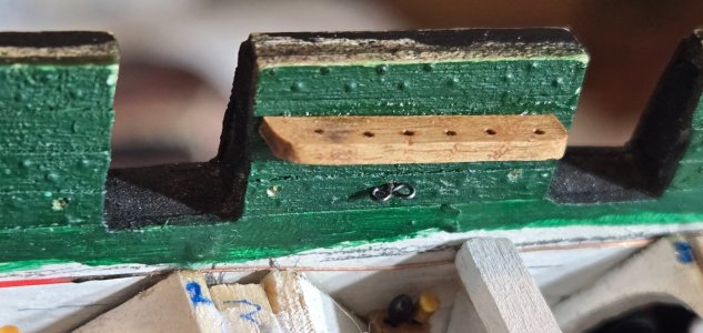
That's it for now. Currently working on the 48 hooks that I will need for the tackle. These too are made from fish hooks, I just cut the shank a bit longer and bend them to shape. Once those are finished, I'll get started on rigging all the tackle that will be used. These take a while
I had thought there was going to be alot more to do to the bulwarks, but apparently for my time period, that's about it. So, it was time to get ready for all the carronades, starting with the eyebolts. As I have mentioned before, I use fish hooks for my bolts. Just cut the eye off using the appropriately sized hooks. Although I don't plan on installing the inhaul tackle, I went ahead and put these eyebolts in place. I drilled the holes for the breech line ring bolts, but these wont be installed now. It is much easier to attach and seize the breech line to the ring bolts and then put them into the bulwarks when the gun is glued to the deck. The last to be done is the double eyebolts for the training tackle. These I made by hand using 28 ga. wire. I tried using Mustafa's method of making two loops at each end of a piece of wire and then folding it in half, but with this tiny wire, I found it more difficult than my original way of looping it around two closely spaced pins
I installed the cleats near the transom and also under the sheave up by the Mizzen mast. I also installed the steps on the transom, which in this period were in the corners not the middle as they are today, and the small iron cleat for the gaff vangs
I had thought there was going to be alot more to do to the bulwarks, but apparently for my time period, that's about it. So, it was time to get ready for all the carronades, starting with the eyebolts. As I have mentioned before, I use fish hooks for my bolts. Just cut the eye off using the appropriately sized hooks. Although I don't plan on installing the inhaul tackle, I went ahead and put these eyebolts in place. I drilled the holes for the breech line ring bolts, but these wont be installed now. It is much easier to attach and seize the breech line to the ring bolts and then put them into the bulwarks when the gun is glued to the deck. The last to be done is the double eyebolts for the training tackle. These I made by hand using 28 ga. wire. I tried using Mustafa's method of making two loops at each end of a piece of wire and then folding it in half, but with this tiny wire, I found it more difficult than my original way of looping it around two closely spaced pins
After cutting to size, I heated them up with a torch until red hot, which blackened them
That's it for now. Currently working on the 48 hooks that I will need for the tackle. These too are made from fish hooks, I just cut the shank a bit longer and bend them to shape. Once those are finished, I'll get started on rigging all the tackle that will be used. These take a while
Moving along nicely there Frank. I'm glad that you're two nail double eye bolt bending tool worked well. I tried that and found mustafa's method easier. Lastly, can you tell me what size and brand of fish hooks you're using?
Hi Peter,
With a slightly larger wire, I could see where his method would be easier. For me, with such a small wire, I could easily pull the circles tight so they are nice and uniform. As for the fish hooks, the brand varies depending on what's available for the size I want, which is typically very small. The larger ones are always available. I buy alot of stuff from Temu. Alot of people on this site use AliExpress, but either way, it's very cheap stuff from China - 100 hooks for $5. If you were rally fishing, you would want good quality hooks, but for what we are doing, these cheap chinese ones are perfect. For us, you want to buy Fly fishing hooks, which are quite small and of course, it's best to buy the ones with a black finish, unless you want the look of brass. Here's a link for the last bunch I bought
 www.temu.com
As for the size, it depends on what size eyebolt you want. here is a list of approximate wire sizes for small hooks
BTW, I just realized that with two sets of tackle per gun, two hooks per set and 24 guns that makes 96 hooks, not 48
With a slightly larger wire, I could see where his method would be easier. For me, with such a small wire, I could easily pull the circles tight so they are nice and uniform. As for the fish hooks, the brand varies depending on what's available for the size I want, which is typically very small. The larger ones are always available. I buy alot of stuff from Temu. Alot of people on this site use AliExpress, but either way, it's very cheap stuff from China - 100 hooks for $5. If you were rally fishing, you would want good quality hooks, but for what we are doing, these cheap chinese ones are perfect. For us, you want to buy Fly fishing hooks, which are quite small and of course, it's best to buy the ones with a black finish, unless you want the look of brass. Here's a link for the last bunch I bought
100pcs fly fishing dry fly tying hook standard wire barbed - Temu Canada
Shop 100pcs fly fishing dry fly tying hook standard wire barbed dry fly nymph nickel end fly tying material size 14 16 18 20 22 at the lowest price at Temu. Check reviews and See of sports & outdoors. .
As for the size, it depends on what size eyebolt you want. here is a list of approximate wire sizes for small hooks
- Size 22–24: 0.008" – 0.010"
- Size 16–20: 0.012" – 0.016"
- Size 12–14: 0.018" – 0.022"
- Size 8–10: 0.024" – 0.028"
- Size 4–6: 0.030" – 0.038"
The hole of the eye will be pretty much the same as the wire diameter, so the overall diameter of the eye will be 3X the thickness of the wire.
BTW, I just realized that with two sets of tackle per gun, two hooks per set and 24 guns that makes 96 hooks, not 48
Hmmm, heating them will probably ruin the brass finish. As you may recall, I am not doing Connie in the black and white scheme most others are. and I'm trying for shiny brass wherever metal is deployed in the kit. So, heating is not presently in the cards. ...Though I am experimenting with soldering the irons for the jibboom stays.hooks are made of hardened steel so they will snap if you try to bend them. If you are going to bend them, like making hooks, you need to soften the metal, which is easy to do. Just heat them up with a torch and let them cool down slowly. Hope that helps. Let me know if you have any other questions.
I don't like using Chinese vendors like Temu or Ali-Baba, so I'll have a look at Bass Pro's fly fishing section next time I'm in that neck of the woods. At this point, I could probably just continue to bend my own eyebolts, and save myself the expense. There can't be many left to install on my build. (at least I hope not).
Stay cool every one.


Just catching up with about a week's worth of Frank's build log here. FWIW, I also have Olaf Eriksen's book. A very interesting read... and the diagrams themselves will be really helpful in rigging.I originally found the 1812 Isaac Hull Model at the Peabody Essex Museum on the Fine Scale Modeler site. Then I supplemented the collection as I found various images on other sites. (I have a total of 75 images) When I checked the original link to Fine Scale Modeler, all the text was there but the images were not, just placeholders. The text does have a link to an excerpt from Constitution All Sails Up and Flying by Olof A. Eriksen which gives a history of the model. If you have a copy of that book, the text begins on page xxii.
Jon
I am not a fisherman, but the fish hooks application may be quite helpful. And I have a Bass Pro Shop within a 10 minute drive from me.
Hey Gregg, thanks for popping in. Peter, you are absolutely right. Heating the fish hooks darkens them up. They are not solid brass, which you can heat without losing its color. Fish hooks are just plated and when you heat them with a torch, you basically burn off the brass leaving just the steel. Fortunately I don't think you'll need any hooks from here out. For straight eye bolts you'll be good

- Joined
- Mar 20, 2026
- Messages
- 63
- Points
- 78

With all the pin rails finished and in place I was ready to move on to the other bulwark details starting with the cleats. The kit supplies 8 large (5/16") cleats made from Brittania metal. I decided to make these out of wood for a much better look. The Navy plans for these cleats (Plan #28433) gives al the dimensions. They are essentially 8.5" square and 47.5" long and shaped accordingly. I saw three ways of shaping these. First was to use square stock, cut to length and file/sand away the bottom half on each end to make the cleat. I didn't like this as I saw it being difficult to reproduce exactly several times. The next would be to sandwich two thinner pieces of different lengths to make the shape of the cleat. Although this seemed to be a bit more reproduceable, it also seemed like a lot of fiddy work. I finally decided the best approach would be to use a piece of flat stock that was 0.5"x.090" and run it edgewise through the Byrnes saw with the depth set appropriately to trim off the bottom half on either side. This gave me the shape of the cleat which I could then slice off like bread using the chop saw
View attachment 617284 View attachment 617283
Once cut, I drilled a hole in the center for a pin. A little stain and some black dots for the other "bolts" and they were done
View attachment 617285
Great job gives me ideas when I start my wood kit
Here's where i ran into some trouble. The BJ instructions once again proved to be a source of frustration. The actual instructions for the spar deck construction make no mention of any cleats. The belaying plan in the back of the book do mention cleats, but with little detail and I believe some missing information. here is the plan
View attachment 617286
The first thing to mention is the note in the far right corner. It states that numbers = belaying pins or cleats. As far as I can see all the numbers on this diagram point to pin rails. No cleats. Next, if we look closer at the bow, it does mention cleats, but provides no details
View attachment 617288
Although it clearly shows some different sized cleats, the larger of course being the large wooden cleat. It only shows four small cleats, whereas there are 5 0n the actual ship. Three wooden ones that appear to be slightly larger than the two iron ones close to the cathead. The kit provides two sizes of small photo etched brass cleats. For now, I am going to assume that the one directly above the cathead was simply omitted in the drawing and that there are five smaller cleats here. As we move aft, you can see that there is no mention of the large wooden cleat that is currently just forward of the waist. Again, I am going to presume that this large cleat should be here.
Looking at the aft end of the plan, there are more missing details
View attachment 617287
You can see that there is no mention of the large wooden cleats currently just aft of the waist and just in front of the davit just forward of the mizzen channel. As we get to the transom, there is again mention of some cleats. The apparent size of the cleats is similar to the large cleats on the bow, however, the ones currently on the ship are the smaller wooden ones. I guess I will assume that the ones drawn here simply aren't meant to be to scale. In addition to that, the diagram indicates an eyebolt in the deck for the gaff vangs (denoted "B" inside the red circle). The ship currently has cleats in the corner of the transom, and interestingly, the Revell model shows those cleats present and intended for the gaff vangs. Seems to me that a cleat would be more appropriate for this tie off?
Lastly, there is the cleat indicated in the center of the transom, aft of the boom traveler. Currently, this cleat appears to be in the deck forward of the traveler, perhaps because of the gunport there now. Regardless, there once again is no indication of the size of this cleat, although looking at the real ship, it appears to be one of the smaller iron ones.
I guess at this point, I am going to use the current ship for guidance and position the cleats as they are on the ship now, although I would welcome any comments from those of you who might know better. One last detail, there are 8 of the large cleats provided in the kit. If we take into account the ones missing in the diagram above, there would be 8 needed.