• Ships of Scale has incorportated an extra level of security when you log In. Please follow on-screen prompts to acknowledge that you are not a robot via a "Check Box" or a "Pictorial Check Box Puzzle". This is needed due to higher level of AI Activity Security.
  • SUBSCRIBE TO SHIPS IN SCALE TODAY!

    The beloved Ships in Scale Magazine is back and charting a new course for 2026!
    Discover new skills, new techniques, and new inspirations in every issue.

    NOTE THAT OUR NEXT ISSUE WILL BE July/August 2026
  • Win a Free Custom Engraved Brass Coin!!!
    As a way to introduce our brass coins to the community, we will raffle off a free coin during the month of August. Follow link ABOVE for instructions for entering.

BALDER, Vlaardingen Herring Lugger from 1912, scratch build scale 1:50 Plate-On-Frame

I have to admit, I didn't even realize she didn't have an engine! It certainly wasn't because I wasn't paying attention to your build. Quite the opposite, I was so captivated by the model itself and by watching your construction process unfold that I never stopped to think about the propulsion.

What really held my attention was the incredible level of detail and the way you've captured the character and appearance of the original vessel. Every update revealed another beautifully executed feature, making it feel less like looking at a model and more like seeing the real ship in miniature. That's a real credit to your craftsmanship, Peter. Thanks for teaching us something new about these wonderful old herring luggers, and congratulations on one of the unique builds you share.
You also thanks for this nice words and compliments, Jim.:) That I managed to keep you ‘on the dark of the moon’ for almost 3 years regarding her propulsion ……. ;) This quote of yours is very essential: “keep the character and appearance of the original vessel”. I can do this thanks in part to the attentive members here at the SoS, but also to the members of the Balder Foundation. It keeps me sharp until the end.
Regards, Peter
 
Last edited:
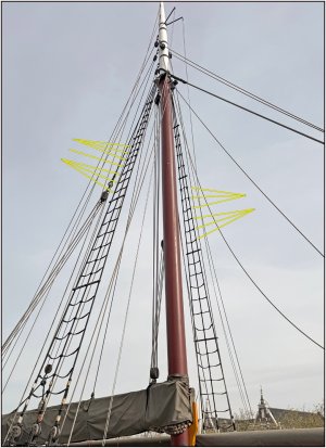
While making the 46 ratlines from the 0.25 mm wire with 2x2 stitches for the eye splices, you have to do something else every now and then.
The forestay made to size.
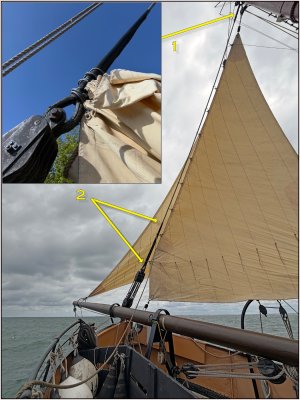
The example:
1182 Voorstag.jpg
At the top (1), it is attached to the mast with an eye splice.
At the bottom, it is attached to the upper metal 4-sheave block with an eye splice and metal eye.
On the 1:1 Balder, a rubber shoe has been fitted around the stay at the bottom (2). The 10 rings of the jib are caught over this. Presumably to prevent chafing and to ensure the eyes do not get caught on anything.

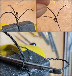
The forestay is made of 0.8 mm rope. That is thick enough to make a proper eye splice:
1183 Voorstag.jpg
1: I have temporarily secured the folded end with a thin thread. You thread the middle loose strand through a fixed strand first. This is how you start by getting the 3 strands each at 120 degrees.
2: The next step is to thread each of the 3 strands diagonally from right to left over a fixed strand and then under the adjacent strand. After all 3 strands, you will have them each at 120 degrees again.
3: I use a small sail needle to thread through. It is triangular and has a slightly blunted tip, which makes threading easier. It also has a somewhat larger eye so that you can easily get the loose strand into it.
After each threading, pull all 3 loose strands a little tight and, if necessary, roll them between your fingers so that they lie neatly in place. Then repeat this until your splice has the desired length.

The result:
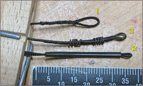
1184 Voorstag.jpg
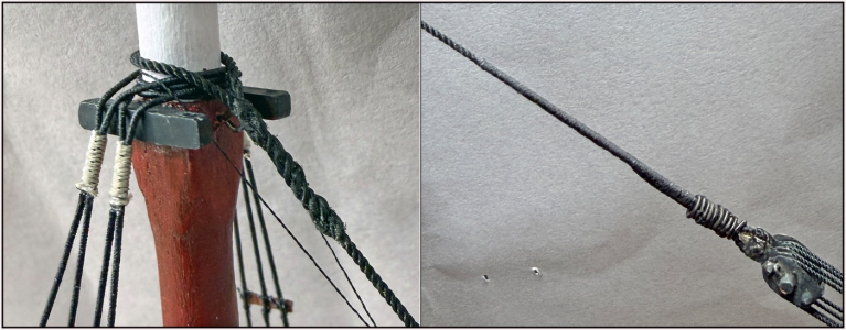
1: The eye splice for around the mast.
2: A test to replicate the original using thin heat shrink tubing. But that is too coarse for me, and the 2.5 mm eyes for the jib do not fit over it.
3: Opted for a served splice where I shortened the 3 strands in 3 steps to varying spacing. First, I slid the 10 rings over the eye and then inserted the metal eye.

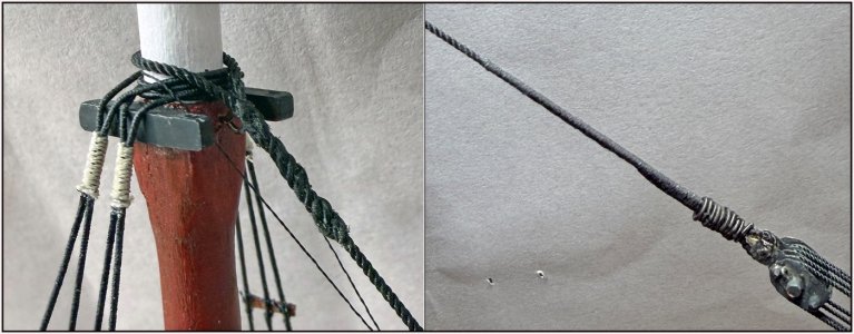
On my temporary setup:
1185 Voorstag.jpg
On the left, the eye splice around the mast, and on the right, the served splice with the metal eye around the pin on the metal 4-sheave block.
Regards, Peter
 
Fantastic miniature work Peter. The type of treading rope your using looks like it might lend itself well to fashion a Molly Hogan type loop. We used this method when rigging our cranes. Google search it and I think you will be surprised.
 
Fantastic miniature work Peter. The type of treading rope your using looks like it might lend itself well to fashion a Molly Hogan type loop. We used this method when rigging our cranes. Google search it and I think you will be surprised.
Thanks for pointing this option, Daniel. Just found an instructive video. I keep that in mind.
Is it correct that you need a thread with an even number of strands for a neat Molly Hogan?
Regards, Peter
 
Thanks for pointing this option, Daniel. Just found an instructive video. I keep that in mind.
Is it correct that you need a thread with an even number of strands for a neat Molly Hogan?
Regards, Peter
I have actually made molly hogans but to be honest I just separated the strands at approximately but not always even sides. You would just have to experiment with it. I do know the stiffness of 1/2" or 3/4 " cable actually helps to facilitate the procedure, not sure how a soft material would work. Seeing the manufactured twist in your rope is what made me think of it.
 
Peter, my dear friend
very beautiful model!
Your attention with accuracy for all the small parts and your great ability to replicate to the smallest detail is a wonder in itself. Your build is astonishing in the modelling area
 
Peter, my dear friend
very beautiful model!
Your attention with accuracy for all the small parts and your great ability to replicate to the smallest detail is a wonder in itself. Your build is astonishing in the modelling area
You also thanks for the nice words and compliments, Shota. It’s sometimes nearly to my limit’s ……. but they shift …..
Regards, Peter
 
I had already mentioned that I had started on the ratlines. It involves doing it in stages to give the eyes a little rest after each block:
1186 weeflijnen.jpg
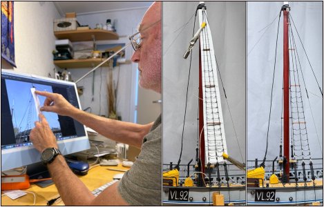
Based on the 1:50 scale, I brought a photo of the 1:1 into view in Photoshop at the correct dimensions to make a template. My Admiral thought it would be fun to take a photo of it.:)
I now have 2 blocks of 6 ready.

Through the photo of the 1:1, I encountered another 'eyebrow moment' regarding the 'professional rigger' of the standing rigging after the installation of the new masts. I had already noticed that many blocks were not hooked in the described manner.
While working out the template for the distances in the 3rd block of ratlines, I discovered that the rigger had put 7 on the starboard side and 6 on the port side in that block ..........;)
1187 weeflijnen.jpg
So far, I haven't read a single specification stating that the two shrouds should have a different number of ratlines........ :(
..... the things that Voogt pays attention to...... I decided not to make that detail on my model.:rolleyes:
Regards, Peter
 
Last edited:
The mainmast is offset to port of the centerline to allow it to clear the mizzen when lowered, correct? Logic would dictate that the starboard shrouds would be longer than the port ones. While it may seem an insignificant amount, is it possible that it is just enough to require an extra rank of ratlines lest the spacing be too great for comfort/safety if left the same as the port side?
 
Very good eye for detail to catch the Even to Port and Odd to Starboard!
Thanks, Brad.
Looks great, even if you are now deviating from the actual ship's ratlines. :D
That’s for sure. The model is a compromise between the old specification, the 1:1 and the impossibilities of my two-halves-model.:) That has an advantage ....... if someone points out an imperfection on or in the model to me, my question will be: based on what reference? I can justify (almost) anything.ROTF
Regards, Peter
 
The mainmast is offset to port of the centerline to allow it to clear the mizzen when lowered, correct? Logic would dictate that the starboard shrouds would be longer than the port ones. While it may seem an insignificant amount, is it possible that it is just enough to require an extra rank of ratlines lest the spacing be too great for comfort/safety if left the same as the port side?
That is an interesting line of reasoning, and I greatly appreciate your input, Russ.
Due to the twisting of the mast and the placement of the shrouds, a few different small angles occur.
1. The shrouds are positioned perpendicular to the slightly rotated mast on both sides, rather than perpendicular to the ship's longitudinal axis: slightly further forward on the port side and slightly further aft on the starboard side.
2. Which also makes the combined angle of the assembly of the 3 shrouds on both bulwarks just slightly different: due to the forward placement, there is a slightly smaller angle on the port side and a slightly larger angle on the starboard side, relative to the top of both bulwarks.
But in terms of length, that shouldn't make any significant difference.

Given my findings in post #2745 during the lowering of the mast, the final pivot point lies around the deadeye hook of the middle shroud. At the start of the heeling, it drops slightly, only to pick up again later to end in its starting position. The same happens on both sides.
In my opinion, the differences in those angles are not significant enough to explain the extra ratline in order to a extra length of the shrouds. The distance between the ratlines is, after all, around 36 cm.
All in all, grounds to take some extra measurements on the 1:1. Let's see where the difference originates or is caused. And perhaps do some old fashion geometry drawing and calculations.:) There are a number of triangles that are related to each other.
Regards, Peter
 
Last edited:
Back
Top