BALDER, Vlaardingen Herring Lugger from 1912, scratch build scale 1:50 Plate-On-Frame

Joined
Jun 19, 2020
Messages
5,148
Points
738

Location
Woudrichem, Netherlands
It's time for a new build-log.
Towards the end of the build of my Bluenose, there was the thought of what to building.
Of course, that had to be a challenge (again).
I had already suggested building a Vlaardingen herring sail lugger from around 1900.
My place of birth is Vlaardingen, and my grandfather was a herring cooper. He made barrels for herring fishing. So, the choice becomes a lot easier.
I already posted this picture:
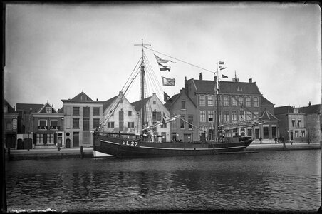
0001 Vl27.JPG
If you take a closer look at the picture, on the back is a wheelhouse, so apparently the old VL.27 has been modified. The old lugger had a tiller on the open aft deck.
After that several loggers passed and I went through the list of Vlaardingen loggers on this site:
--> List of VL-luggers <--

The choice was soon reduced to a 'riveted steel sail lugger' from around 1900.
And my intention was to completely copy it in terms of construction, so with frames and rivets. For that I had to have clear construction drawings.
I have consulted many sites and caves of the internet, but in the field of construction drawings ………… almost nothing to find. Except for 1 source ………….
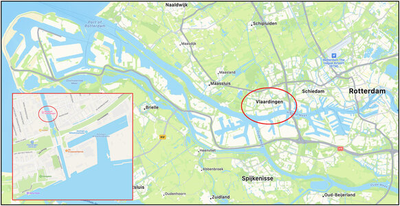
The 'Balder' I mentioned earlier. The restored sail lugger that is now in the harbor of Vlaardingen. The ship is owned by Stichting Museum Vlaardingen (SMV), the former Fisheries Museum, and has been transferred on loan to Stichting Zeillogger Balder (SZB).

History of the Balder: (largely taken from the restoration book of the SZB)
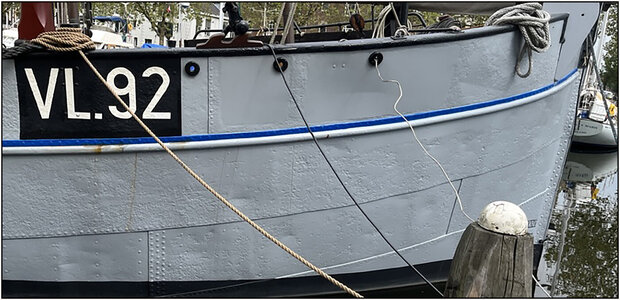
The Balder was built in 1912 in Vlaardingen at the yard of A. de Jong on behalf of ‘Visscherij Maatschappij Mercurius’. She served as VL.92 Balder until 1921:
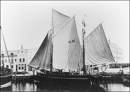
0002 vl-92.jpg
In 1929 it was sold to the Scheveningen shipping company Arie van der Zwan and was named SCH.14 OCEAAN. The ship owner has lengthened the ship and put an engine in it.
During WW-II it was requisitioned by the occupiers. After the war she was used again for fishing.
Until 1976 she was used as ZEEAREND as a training ship for the fishing industry in Scheveningen.
In 1977 she was transferred to the Scheepvaart Museum in Amsterdam for 1 guilder. There she was restored for 10 years, brought back to her original length and added to the collection. They made a nice book of that restoration :
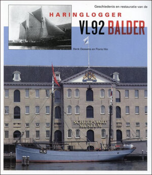
0003 Amsterdam.jpg
The project leader of the restoration, Sybe de Jong, has made a model of the Balder that is still in the collection of the Scheepvaartmuseum:
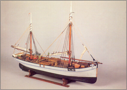
0006 Model.jpg
In 2006 she was transferred to the SMV for 1 euro in bad condition.
After a preparation of 2.5 years, she left on 06-12-2013 for restoration to the Bocxe shipyard in Delft. Of this restoration, the SZB made also a restoration book:
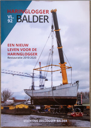
0004 Rest SZB.jpg
The test run was held on 22-09-2016 and then moored in the port of Vlaardingen with a berth for the SMV:
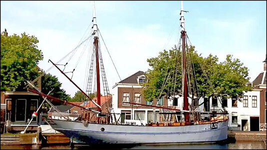
0005 Vlaardingen.jpg
--> SZB web-site <--
--> Inter-active BALDER website <--
I have been a donor to the SZB and have contacted the chairman to obtain more information from the Balder. I spoke extensively with him.

More to come ......
Regards, Peter
 
Last edited:
Herring fishery:
I will explain it with a drawing and the Dutch names. I suppose the translation sites will ruin the specific names.
0007 Vleet.jpg
The ‘Vleet’ or ‘Reep’ was used for herring fishing. The Balder belongs to the last generation of sailing ships with which this age-old technique was practiced. It originated around 1400 from the old driftnets.
At the time of the Balder, a vleet consisted of 70 nets that hung vertically in the sea and were tied together. Each net was 31.5 meters long and 15.5 meters deep.
The whole was set out and reeled in via the Reep that hung at a depth of about 6 meters. This rope hung at the end of 6 meter long breel ropes, each of which was attached to a breel. A breel floated on the water per net. Breels are watertight wooden barrels.
Seizings hung 8 meters down and were connected to the speerreep. This rope was connected along the entire length of the nets and kept the net afloat with a multitude of cork flotillas. The nets themselves were fastened together with zijpezen.

History of the lugger: (largely taken from the restoration book of Scheepvaartmuseum)
The logger originates from France. In the Netherlands the buis, bomschuit or the hoeker were in use. The Scheveningen shipowner A.E. Maas ordered a new 3-mast lugger in Boulogne in 1866 and brought it to the Netherlands. Scheveningen itself had no harbor at that time, so the ship was brought to Vlaardingen. Soon Maas ordered 2 new luggers that were made at Vlaardingen yards.
Until the beginning of the 20th century the luggers were made of wood, but around 1880 the first steel luggers were built.
The 1st 3-mast luggers from Maas had bucket sails. (I don’t know if this is the correct translated name for that rigging/sails.) The Dutch fishermen did not like this and soon they became 2-masted luggers with cutter rigs: a foremast and a mizzen mast, each with gaff sails.
Lying ‘aan de vleet’ the foremast was partly lowered, and the mizzen kept its head in the wind.

No sailing seagoing fishing vessel was preserved in any Dutch museum collection. Hence the interest of the National Maritime Museum.
The Balder is the only lugger that is almost in its original state.

Vlaardingen:
Of a fleet of around 500 sail luggers that have been fishing in the North Sea since the end of the 19th century, there were no less than 165 in the port of Vlaardingen. It was then one of the largest fishing ports in Europe. There were several shipyards and also a large processing industry for the caught herring.
0008 Vld.jpg

Building in what scale:
Initially the intention was to build in the same scale as the Bluenose, so 1:72. Then the question is, is that feasible with Evergreen and rivets to scale?
I first assumed 1:50, because that is easier to calculate and a common scale for adding the necessary details.

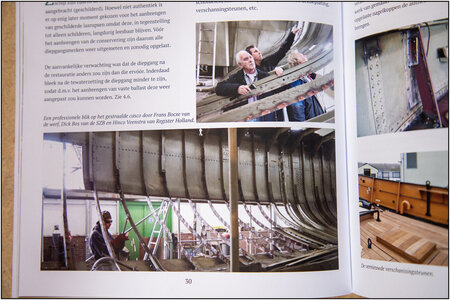
The model is constructed from metal angle profile frames. A photo of some of those frames during the restoration:
0009 Frames.jpg
(Source: The restoration boek of the SZB)
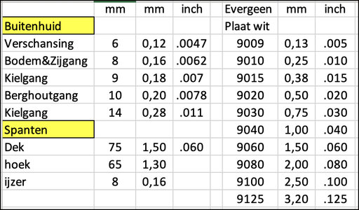
I have taken the following dimensions from the old specifications described in the restoration book of the Scheepvaartmuseum.
The frames in angle profile and different outer skin plates:
0010 Maten.jpg
In terms of hull plates, Evergreen has the 9009, 9010 and 9015 for that. But if I must smuggle a little more because of the firmness, then there are more sizes available.
I took the frames also in the comparison because these will be the width of the strips in which I have to drill holes for the rivets.

A few tests:
Strip of 2.5mm:
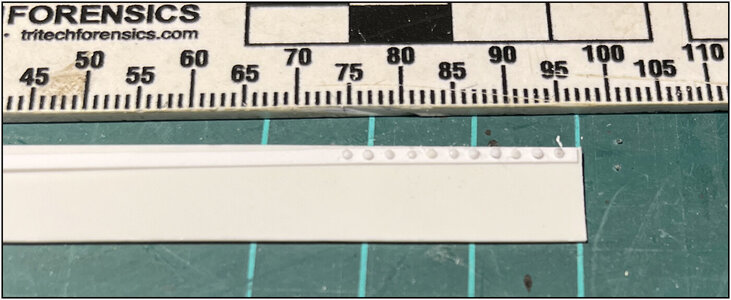
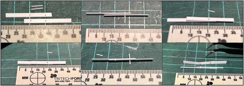
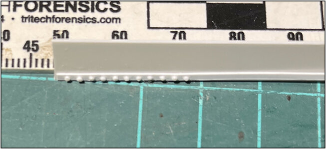
For the rivets I took ø 0.5 mm Evergreen rod. First made a latch on 1 side with the tip soldering iron. Then inserted through the ø 0.6 mm holes, cut to 1 mm and the other side 'riveted' with the soldering iron. So you have to be careful not to get too close to the strip to avoid distortion.
0011 Test 2-5.jpg
Strip of 1mm:
Ditto, but it becomes very tight with a drill of 0.6 mm to have some meat left on both sides. Put this aside for now.

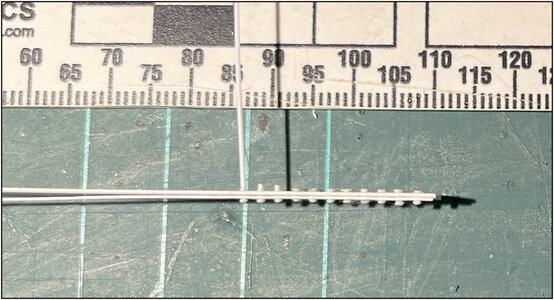
A 1.5 mm strip fixed to a plate, with a rivet every 2 mm.
First drilled the holes in the strip, the first 2 rivets and a few more:
0012 Plaat-1.jpg
With as detail 2 rivets cut to size, without riveting and a pulled through rod:
0013 Plaat-2.jpg

With the result:
0014 Plaat-3.jpg
0015 Plaat-4.jpg

But the little bulbs are too big. Especially if you see this example:
0016 Klinknagels.jpg
And then also the old description:
The nail holes must be filled out to 2/3 of the plate thickness.

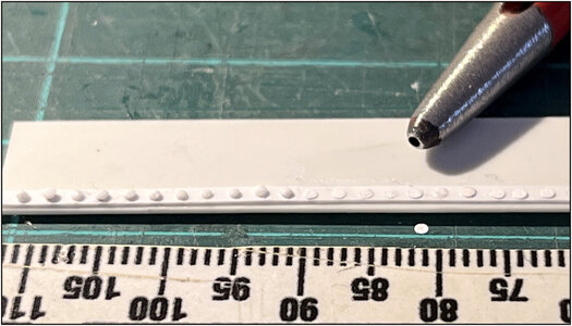
Seeing the rivet balls of +/- 1 mm I thought of my railings of the Robt. E Lee. Where I hit rounds of 1 mm with the hollow pipe.
Looks more promising:
0017 Klinknagels.jpg

Small balls of paint or glue may also be an option. But try making them all (several thousands) the same size …….. ;)

Given these dimensions, I assume that the scale will be 1:50. Even smaller will be a very bad test …….
Internationally, many models are built at 1:48. But because I must take a lot of calculations it will save me a lot of work with the scale of 1:50.

More to come .....
Regards, Peter
 
Last edited:
Wonderful Peter. Looking forward to following another remarkable build. If I must I’ll squeeze in next to Jim - I just hope he behaves this time. Otherwise I’ll have to move closer to Uwe and Tobias but my German isn’t strong…
Just wonder what I did last time... :p
 
Wonderful Peter. Looking forward to following another remarkable build. If I must I’ll squeeze in next to Jim - I just hope he behaves this time. Otherwise I’ll have to move closer to Uwe and Tobias but my German isn’t strong…
Hi Paul. You are also very welcom. When unrest arises:
IMG_3742.jpeg
Yes, the work room of ‘PeVo-Models’ has limited space.......
Regard, Peter
 
Peter, here is something to try on the rivets… take a very thin evergreen rod and shave off slices. Take a lighter flame and pass it over the slices and it makes them take a curve on the upper surface and remain flat on the bottom. You will need to experiment with getting the proper thickness of slice and develop a method to assure consistency. I suspect you will have too many rivets for this technique but it might be worth a shot. I saw Marc (@Hubac’s Historian) do this on his current project and was able to replicate it on the stove for the Kingfisher (only to later learn that I needed to use square headed bolts and took them all off). Anyway, it might be worth an experiment when you’re done moving chairs around.
 
Peter, here is something to try on the rivets… take a very thin evergreen rod and shave off slices. Take a lighter flame and pass it over the slices and it makes them take a curve on the upper surface and remain flat on the bottom. You will need to experiment with getting the proper thickness of slice and develop a method to assure consistency. I suspect you will have too many rivets for this technique but it might be worth a shot. I saw Marc (@Hubac’s Historian) do this on his current project and was able to replicate it on the stove for the Kingfisher (only to later learn that I needed to use square headed bolts and took them all off). Anyway, it might be worth an experiment when you’re done moving chairs around.
Thanks for pointing this option, Paul.
I think I have to make more rivets then treenails on my BN. I’ll make a try with a row of slices.
Regards, Peter
 
Peter, here is something to try on the rivets… take a very thin evergreen rod and shave off slices. Take a lighter flame and pass it over the slices and it makes them take a curve on the upper surface and remain flat on the bottom. You will need to experiment with getting the proper thickness of slice and develop a method to assure consistency. I suspect you will have too many rivets for this technique but it might be worth a shot. I saw Marc (@Hubac’s Historian) do this on his current project and was able to replicate it on the stove for the Kingfisher (only to later learn that I needed to use square headed bolts and took them all off). Anyway, it might be worth an experiment when you’re done moving chairs around.
I like this suggestion, but like you already mentioned; it will be quite a feat to have a consistent head shape for all these thousands of rivets. It's as if one needs an electric solder torch with a very wide temperature range (also at the lower end if the spectrum) and a modified solder head with the required head shape. (Peter, didn't you use something similar for some bolts in the spiderlegs/keel connection of your Bluenose?) Even then, both the rivets as the sheets are made of the same material with no heat sink capabilities to speak of, so theres potential risk of ruining the required appearance. It looks as if you have to replicate to some extent, at scale 1:50 and in thermoplastics the old school riveting process.
Another option might have been copper rivets, but, apart from having proper head dimensions, the form on set head on the inside is off.
 
This has large potential of being a very interesting build, not in the last place because it's unique in every sense of the word.
A new impulse to modeling of long forgotten Dutch ships.
Thanxs, Johan.
To be able to make an interesting report, I want to place photos, text and drawings. I have already received many files from the Balder Foundation. I must have their permission to post. But several of them are also included in one or both restoration books. I have submitted a request to the foundation and the publishers to be allowed to place it in my report.
Then I can make a new post.
Till then busy to get 54 seperate line drawing of the shape of the frames ….. ;)
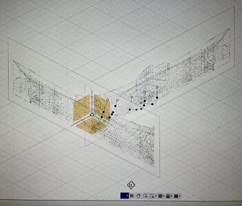
Started a CAD program to import the line drawing plan. Using it, drawing new lines to get a 3D model.
Regards, Peter
 
For those interested a little preview: in Fushion 360, drawn in the Y-line drawing (width), projected at the bow in the X-line (length) drawing, the first 5 Station Lines started from the bow. And transferred in the X-line drawing (length) in the length from the bow till midship:
IMG_8890.jpeg
When you know how to do ……. Then it is …… But before you know ……. RTFM
And the used lineplan:
IMG_8891.jpeg
(Source: Drawing from the SZB)
Now I have to flip the Y-line drawing to draw the 7 line till the stern.
Regards, Peter
 
Last edited:
Back
Top