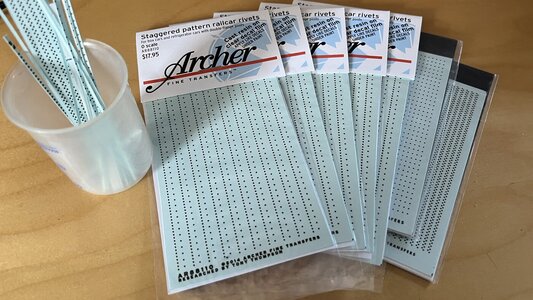
Great resource - many thanks for the response
-

Win a Free Custom Engraved Brass Coin!!!
As a way to introduce our brass coins to the community, we will raffle off a free coin during the month of August. Follow link ABOVE for instructions for entering.
-

PRE-ORDER SHIPS IN SCALE TODAY!
The beloved Ships in Scale Magazine is back and charting a new course for 2026!
Discover new skills, new techniques, and new inspirations in every issue.
NOTE THAT OUR FIRST ISSUE WILL BE JAN/FEB 2026
You are using an out of date browser. It may not display this or other websites correctly.
You should upgrade or use an alternative browser.
You should upgrade or use an alternative browser.
BALDER, Vlaardingen Herring Lugger from 1912, scratch build scale 1:50 Plate-On-Frame
- Thread starter Peter Voogt
- Start date
- Watchers 65
- Joined
- Oct 28, 2018
- Messages
- 760
- Points
- 403

Nice Work PeterA bit from the same point of view.
Thanks, Henk. Nice to hear from you again.Nice Work Peter
Regards, Peter
I love the detail in your work Peter. Your technical explanations are challenging but fascinating to follow.
Thanks very much, Daniel. For sure it's technical. A lot of hours above the old drawing to fully understand how everything fits together. And for the most: what first, what after that, what before that beam etcI love the detail in your work Peter. Your technical explanations are challenging but fascinating to follow.
Regards, Peter
Good evening Peter. And now we have the evidence needed….Mr Peter Voogt is insane…confirmed! On a serious note, what you achieve boggles the mindBefore making the bilge profile, some preliminary work was done:
View attachment 443710
At the start of construction I had placed an Evergreen rod from the front along the bulkheads to the back on both sides. To keep everything stably aligned.
-Installed this rod again, see arrow A. The rod was kept at the correct height with some supports. The sides of the frames followed that rod nicely.
-Then the profile of the bilge could be held outside and bended in the correct shape: running slightly upwards and following the line of the hull, see arrow B.
-Then positioned the profile at the correct angle, see inset with arrow C. The leg must rest on the reverse frames. The arm must be horizontal to place the floor on it later.
My Admiral couldn't resist taking a photo during fitting and measuring:
View attachment 443711
This won't work without tweezers.
After the necessary fitting and measuring, the bilge scale was secured to the inside of the retaining frames:
View attachment 443712
It follows the rod on the outer side neatly.
Getting started with the 1st floor beam:
View attachment 443713
Also a lot of fitting and measuring.
On the left side the end that fits into the profile in the middle of the hull. With 2 'mannetjes' (little pieces of profile).
There is a lip on the inside of the profile on the right side. To strengthen the connection in the bilge profile. The set-up pieces provided with rivets. I don't think I'll be able to reach that anymore.
Set up the starting position for alignment again and align the 1st floor profile along the wooden pin:
View attachment 443714
The profile sits tension-free between the center and the bilge profile.
Immediately check whether everything is still level:
View attachment 443715
So the construction mold was tilted again on the construction floor.
Both parts against each other:
View attachment 443716
Everything still fits and fits together.
Still 11 floor profiles to go.
Regards, Peter
This is a nice compliment from someone who lives on the same longitude.Good evening Peter. And now we have the evidence needed….Mr Peter Voogt is insane…confirmed! On a serious note, what you achieve boggles the mind. Cheers Grant
My colleagues called it "Pleasantly crazy". But that was more than 5 years ago. Perhaps I am indeed transformed to that next stage ........
Regards, Peter
Then I really go to the next stage and get mad ……..When are you going to sell it as a kit? I bet there's a lot of people out there, itching to build a model like this...
Amazing work, Peter, I'm impressed. You can see the finesse very clearly in the "don't sneeze" picture, a real Sisyphean task. Simply brilliant.
Thanks, Tobias, for your reply with those compliments. I am honored by naming my build as a ‘Sisyphean task’. You raised it to a new level.Amazing work, Peter, I'm impressed. You can see the finesse very clearly in the "don't sneeze" picture, a real Sisyphean task. Simply brilliant.
Being like Sisyphus
But I am sure I will reach the top op the hill.
Regards, Peter
Last edited:
Peter, you are absolutely right. What I meant was that it is very laborious, as it is a very delicate structure. There is no sign of giving up.Thanks, Tobias, for your reply with those compliments. I am honored by naming my build as a ‘Sisyhean task’. You raised it to a new level.
Being like Sisyphus: (Quote from Wiki: The gods forced him to roll an immense boulder up a hill only for it to roll back down every time it neared the top, repeating this action for eternity. (Through the classical influence on modern culture, tasks that are both laborious and futile are therefore described as Sisyphean).
But I am sure I will reach the top op the hill.And I am sure you pointed only at the laborious task …..
Regards, Peter
What a great, accurate, and extremely technical work you are showing Peter.

Last edited:
Thanks for the compliments, Peter. For sure it’s technical. I try to find the most logical construction, based on the drawings. And the information I get from that friend who used to work on the frame building floor and who still have some knowledge of this type of construction. Now I notice that being installing the bilge and the floor profiles for the forecastle, the hull got the correct shape and much more strength.What a great, accurate, and extrely technical work you are showing Peter.
Regards, Peter
The bilge and floor profiles for the forecastle floor were installed in both parts:
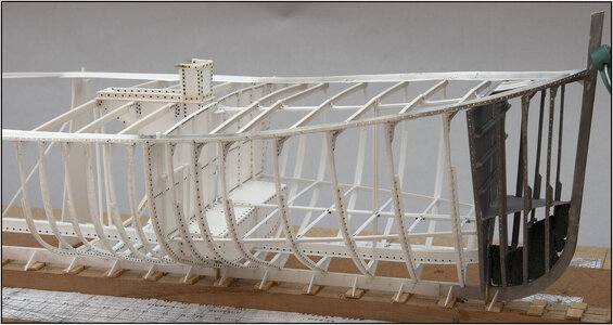
Surprising but also explainable how much extra strength this provides in the front part of the hull.
I also spent a while fitting all connections including knees with rivets:
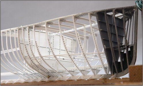
Now it is time to install the rest of the frames with reverse frames almost till te underside of the deck stringer plates.
Picture of the loose starboard part:
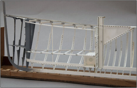
Once the intermediate frames are also included, the hull shape will become even clearer.
PS:Based on the pictures, a few rivets were slid into place.
Regards, Peter

Surprising but also explainable how much extra strength this provides in the front part of the hull.
I also spent a while fitting all connections including knees with rivets:

Now it is time to install the rest of the frames with reverse frames almost till te underside of the deck stringer plates.
Picture of the loose starboard part:

Once the intermediate frames are also included, the hull shape will become even clearer.
PS:Based on the pictures, a few rivets were slid into place.
Regards, Peter
Last edited:
Time to order more rivetsThe bilge and floor profiles for the forecastle floor were installed in both parts:
View attachment 445151
Surprising but also explainable how much extra strength this provides in the front part of the hull.
I also spent a while fitting all connections including knees with rivets:
View attachment 445152
Now it is time to install the rest of the frames with reverse frames almost till te underside of the deck stringer plates.
Picture of the loose starboard part:
View attachment 445153
Once the intermediate frames are also included, the hull shape will become even clearer.
PS:Based on the pictures, a few rivets were slid into place.
Regards, Peter
 ...
...A look at the production process:
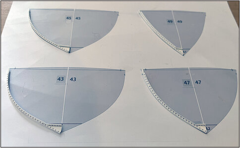
The 4 starboard half frames with reverse frames bent into shape on the Fushion prints:
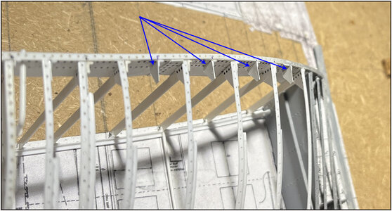
The knee plates with profile against the deck stringer plates:
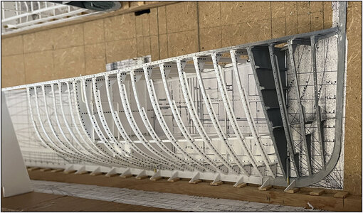
The half frames were first aligned at the bottom and secured between the keel and the keelson:
Then on the bilge profile and at the top against the knee plate.
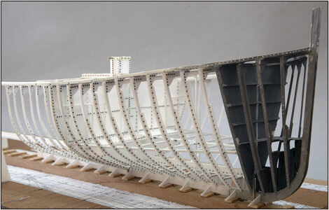
The shape of the hull is becoming increasingly clear:
On to the remaining 4 half frames on the port side.
Regards, Peter
The 4 starboard half frames with reverse frames bent into shape on the Fushion prints:

The knee plates with profile against the deck stringer plates:

The half frames were first aligned at the bottom and secured between the keel and the keelson:

Then on the bilge profile and at the top against the knee plate.
The shape of the hull is becoming increasingly clear:

On to the remaining 4 half frames on the port side.
Regards, Peter
Last edited:
Amazing! And now she starts to look like a ship!
That's for sure, Paul. It was a long road before this came into the picture. Now the other side and the sheet metal on the deck and then she can be released from the slipway for the paint shop. But that will take a while......Amazing! And now she starts to look like a ship!
Regards, Peter
Last edited:


