-

Win a Free Custom Engraved Brass Coin!!!
As a way to introduce our brass coins to the community, we will raffle off a free coin during the month of August. Follow link ABOVE for instructions for entering.
-

PRE-ORDER SHIPS IN SCALE TODAY!
The beloved Ships in Scale Magazine is back and charting a new course for 2026!
Discover new skills, new techniques, and new inspirations in every issue.
NOTE THAT OUR FIRST ISSUE WILL BE JAN/FEB 2026
You are using an out of date browser. It may not display this or other websites correctly.
You should upgrade or use an alternative browser.
You should upgrade or use an alternative browser.
BALDER, Vlaardingen Herring Lugger from 1912, scratch build scale 1:50 Plate-On-Frame
- Thread starter Peter Voogt
- Start date
- Watchers 65
Thanks, Shota. It’s indeed very special, the last days nice weather, but also last Friday a storm with a white-out.It looks like an amazing and very special vacation
Keep enjoying dear friend
Regards, Peter
It took a while, but we are building again at the shipyard.
Started to provide the front with the frames and deck beams.
I had already placed frame 46 with support. Added frame 48:
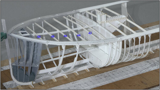
Then I only placed the deck beams of frames 42, 48 and 50. Because then I have a little more time to think about a solution for the following: I have to interrupt both profiles installed lengthwise in the middle.
Looking at the drawings, I had already seen that the following were placed in the middle of the deck: the 'lantern' above the stove in the galley, the entrance to the forecastle and the spotlight above the forecastle.
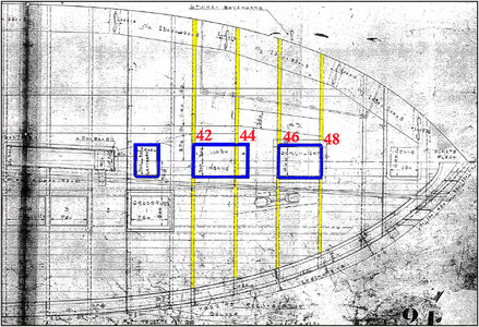
I made the frames for these 3 structures blue.
The entrance to the forecastle is placed on deck beams 42 and 44. Where 44 continues....... That's not logical, you'll hit your head, right?
That's why I visited the Balder again last week.
The 3 structures:
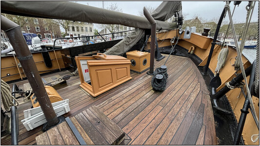
With the entrance to the forecastle:
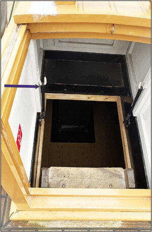
The stairs are at a very sharp angle so that you descend the deck beam 44 backwards. The arrow points to the conversion that was made around and over this deck beam 44.
Also interesting in itself, because the old specifications state that the deck beams in the forecastle are finished all around.
It also becomes clear why the access to the forecastle is made over deck beam 44: there must be sufficient length to be able to slide the hatch forward.
It now gave me the opportunity to check the course of the deck beams with 2 thin strips:
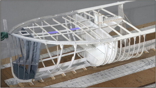
That will be the sheer over the middle of the deck.
In light blue the 2 parts that I have to remove. I will continue with the rest of the frames and making and installing the frames for those 3 structures.
Regards, Peter
Started to provide the front with the frames and deck beams.
I had already placed frame 46 with support. Added frame 48:

Then I only placed the deck beams of frames 42, 48 and 50. Because then I have a little more time to think about a solution for the following: I have to interrupt both profiles installed lengthwise in the middle.
Looking at the drawings, I had already seen that the following were placed in the middle of the deck: the 'lantern' above the stove in the galley, the entrance to the forecastle and the spotlight above the forecastle.

I made the frames for these 3 structures blue.
The entrance to the forecastle is placed on deck beams 42 and 44. Where 44 continues....... That's not logical, you'll hit your head, right?
That's why I visited the Balder again last week.
The 3 structures:

With the entrance to the forecastle:

The stairs are at a very sharp angle so that you descend the deck beam 44 backwards. The arrow points to the conversion that was made around and over this deck beam 44.
Also interesting in itself, because the old specifications state that the deck beams in the forecastle are finished all around.
It also becomes clear why the access to the forecastle is made over deck beam 44: there must be sufficient length to be able to slide the hatch forward.
It now gave me the opportunity to check the course of the deck beams with 2 thin strips:

That will be the sheer over the middle of the deck.
In light blue the 2 parts that I have to remove. I will continue with the rest of the frames and making and installing the frames for those 3 structures.
Regards, Peter
Indeed, Johan, always new challenges to find the solution. It sometimes does not seem logical on the drawings, but in the 1-on-1 implementation the logic is quickly clear. Going down the stairs 'forward' is really not possible. And then 'backwards' poses no problem at all. Certainly not from gangs upwards.Wow, this is far from a straightforward project. It's good to have a full size example to look at; I was rather tempted to think frame 44 would be split by the entrance opening...
Regards, Peter
also interesting to see - necessary for the later deck finishing, that the treenailing of the deck planking and also the butt joints of the deck planks are not following the framing - I guess there is also a steel deck under the wooden planking and the treenailing is following different "rules" if there are any
BTW: very good work
BTW: very good work
Thanks for your post, Uwe. With your eye for details about the treenails and butt joints.also interesting to see - necessary for the later deck finishing, that the treenailing of the deck planking and also the butt joints of the deck planks are not following the framing - I guess there is also a steel deck under the wooden planking and the treenailing is following different "rules" if there are any
BTW: very good work
But these do follow the deck beams. Only during the 2nd restoration did all frames receive a deck beam. While on the old drawings only the deck beams with the retaining frames up to the bilge had a deck beam. The current Balder has been given extra and this can be seen on the photo in terms of rows of treenail plugs. I will follow the old drawings with less deck beams.
Regards, Peter
- Joined
- Oct 23, 2018
- Messages
- 886
- Points
- 403

Wonderful, Peter. I like the really light construction of the steel frameing.
Thanks, Christian. I try to build as close as possible to the measurements of the old drawings, related to the sizes of the used Evergeen profiles. Till now I am satisfied.Wonderful, Peter. I like the really light construction of the steel frameing.
Regards, Peter
This is an understatement Peter…Till now I am satisfied.
Thanks for pointing, Grant. Than I am more and more related to the original Balder. She is also a understatement in the harbor of Vlaardingen: moored between some modern millions of euri costing yachts with flying bridges, GPS domes, remote controlled winches etc. And the Balder with her deck helm, belaying pins with hand ropes, narrow steep stairs etc.This is an understatement Peter…
Regards, Peter
The previously installed deck beams now also have their frames:
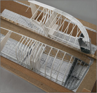
The starboard part on its side, so that everything remains straight and flat in the longitudinal direction during the installation of the frames.
Both parts back together:
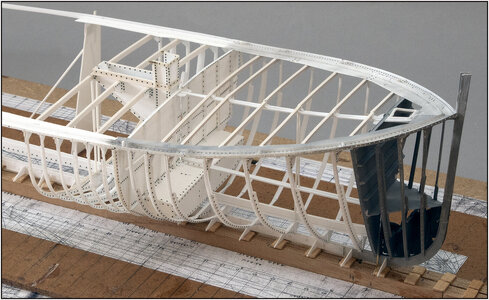
The in-between frames that extend to the edge of the deck without deck beams still need to be placed in between.
But..... now I have space between the frames to install the profiles to support the floor of the forecastle.
These profiles immediately help to create the correct curve in the currently flexible frames. That is in the transverse direction of the ship.
But... those floor profiles are locked between the profile in the middle and the profile in the bilge that I still have to install. And that bilge profile ensures that the still flexible frames are held in place lengthwise direction.
So, changing plans, I will first work on the bilge profiles.
To see whether everything is still in the correct position, I first carried out a check.
When building the Bluenose I had a proven method using wooden satay pins:
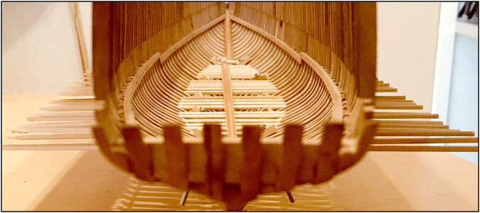
This way I can check the previously installed longitudinal profiles in the middle of the forecastle floor.
With both parts a bit apart, because that length profile also consists of 2 parts:
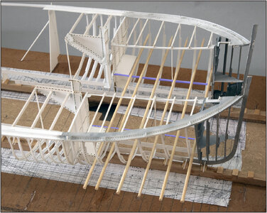
For clarity, I have given those 2 profiles a blue color.
From this point of view the alignment looks good:
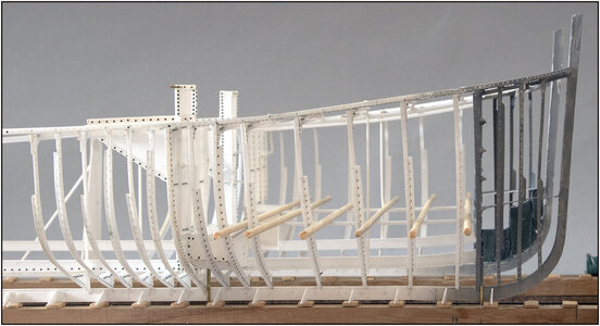
I cannot show straight from the front or the back because my building templates have a right-angled bulkhead on the front and rear sides. To keep the molds perpendicular in a tilted position.
Now I can mark the positions on the frames where the bilge profiles will be placed:
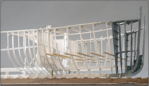
It's just a matter of putting lines on the frames at the bottom of the wood. Then I can bend the bilge profiles into shape and align them with those lines. At the end I will have a flat floor in the forecastle ......
Regards, Peter

The starboard part on its side, so that everything remains straight and flat in the longitudinal direction during the installation of the frames.
Both parts back together:

The in-between frames that extend to the edge of the deck without deck beams still need to be placed in between.
But..... now I have space between the frames to install the profiles to support the floor of the forecastle.
These profiles immediately help to create the correct curve in the currently flexible frames. That is in the transverse direction of the ship.
But... those floor profiles are locked between the profile in the middle and the profile in the bilge that I still have to install. And that bilge profile ensures that the still flexible frames are held in place lengthwise direction.
So, changing plans, I will first work on the bilge profiles.
To see whether everything is still in the correct position, I first carried out a check.
When building the Bluenose I had a proven method using wooden satay pins:

This way I can check the previously installed longitudinal profiles in the middle of the forecastle floor.
With both parts a bit apart, because that length profile also consists of 2 parts:

For clarity, I have given those 2 profiles a blue color.
From this point of view the alignment looks good:

I cannot show straight from the front or the back because my building templates have a right-angled bulkhead on the front and rear sides. To keep the molds perpendicular in a tilted position.
Now I can mark the positions on the frames where the bilge profiles will be placed:

It's just a matter of putting lines on the frames at the bottom of the wood. Then I can bend the bilge profiles into shape and align them with those lines. At the end I will have a flat floor in the forecastle ......
Regards, Peter
Last edited:
- Joined
- Sep 3, 2021
- Messages
- 5,191
- Points
- 738

Hear, hear....Amazing how you can handle these small 'wobbling' parts. Nerve breaking build.
Every detail considered. Wonderful work Peter!
- Joined
- Sep 3, 2021
- Messages
- 5,191
- Points
- 738

I wonder (not really) which ship requires real seamen...Thanks for pointing, Grant. Than I am more and more related to the original Balder. She is also a understatement in the harbor of Vlaardingen: moored between some modern millions of euri costing yachts with flying bridges, GPS domes, remote controlled winches etc. And the Balder with her deck helm, belaying pins with hand ropes, narrow steep stairs etc.
Regards, Peter
Amazing how you can handle these small 'wobbling' parts. Nerve breaking build.
The separate parts are indeed 'wobbling', but as part of a construction they become more and more stable. I am amazed at how clumsily I can sometimes act. Everything stays on its position.Hear, hear....
Regards, Peter
Thanks for the compliments, Paul. All those considerations can sometimes be quite tiring. If you think you have a plan, something comes up ...... But luckily so far it has always been on time. As far as I can consider ......Every detail considered. Wonderful work Peter!
Regards, Peter
Most captains of those fancy yachts hiring an experienced hand as soon as they have to cross even a large stretch of open water. You don't want to know what kind of stories I have already heard from that friend of mine from the yacht building industry.I wonder (not really) which ship requires real seamen...
Regards, Peter

