-

Win a Free Custom Engraved Brass Coin!!!
As a way to introduce our brass coins to the community, we will raffle off a free coin during the month of August. Follow link ABOVE for instructions for entering.
-

PRE-ORDER SHIPS IN SCALE TODAY!
The beloved Ships in Scale Magazine is back and charting a new course for 2026!
Discover new skills, new techniques, and new inspirations in every issue.
NOTE THAT OUR FIRST ISSUE WILL BE JAN/FEB 2026
You are using an out of date browser. It may not display this or other websites correctly.
You should upgrade or use an alternative browser.
You should upgrade or use an alternative browser.
BALDER, Vlaardingen Herring Lugger from 1912, scratch build scale 1:50 Plate-On-Frame
- Thread starter Peter Voogt
- Start date
- Watchers 65
Not sure what to say Peter - the frames just look SO GOOD!
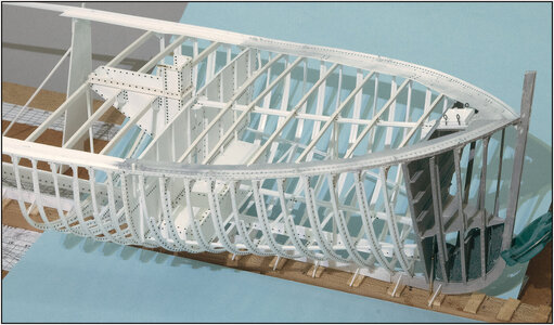
Thanks, Paul. I am also satisfied with the result so far. She's starting to take on the shape of a real ship.Not sure what to say Peter - the frames just look SO GOOD!
Regards, Peter
Thanks, Stephan. After 22 of the 54 frames, time for something else.Big milestone reaching this point. Like Paul said, these frames look so beautiful accurate. It was a lot of work, but we can see a ship now.
Regards, Peter
- Joined
- Sep 3, 2021
- Messages
- 5,190
- Points
- 738

Some really serious modeling: scratch building, but not for the faint-hearted...All the frames of the forecastle are installed on both sides
Hi Peter,
That will be a scary job cutting the deck centre beam to add the coamings with this fragile construction.
That will be a scary job cutting the deck centre beam to add the coamings with this fragile construction.
- Joined
- Sep 3, 2021
- Messages
- 5,190
- Points
- 738

Hi Peter,
That will be a scary job cutting the deck centre beam to add the coamings with this fragile construction.
Cutting the center beam...
….. and shaking hands etcSome really serious modeling: scratch building, but not for the faint-hearted...
There will also be some deck plates and deck stringers. I think I will be able to reassure you in the next update.Hi Peter,
That will be a scary job cutting the deck centre beam to add the coamings with this fragile construction.
Regards, Peter
Well, I am in synch with others (above), unsure how to describe your work... Just WOW, a big one and very loud!!!!!
Well Jim, then from me a big THANKS!!!!Well, I am in synch with others (above), unsure how to describe your work... Just WOW, a big one and very loud!!!!!
Regards, Peter
Good morning Peter. If I could pull something like your work off, I would party for a week. Brilliant modelling Peter. Cheers GrantI am also satisfied with the result so far.
Thanks, Shota. It’s building up step-by-step. And then on a moment it’s ‘YES’, now it starts to look like a ship.Dear Peter
the frames looks incredible
Regards, Peter
Thanks Grant. I will sure to that: Next week I am off with the motorcycle for 9 days touring in France. Then for sure I am looking several times to the build so far.Good morning Peter. If I could pull something like your work off, I would party for a week. Brilliant modelling Peter. Cheers Grant
Regards, Peter
I am envious Peter. I aggravated an old back vertebrae fracture recently and I am off my bike for a while....... nothing like a bike adventure - enjoy. Have fun. Cheers GrantThanks Grant. I will sure to that: Next week I am off with the motorcycle for 9 days touring in France. Then for sure I am looking several times to the build so far.
Regards, Peter
I can empathize with your situation, Grant. In 2006 I broke 3 lumbar vertebrae. But still (nok-nok on wood ……I am envious Peter. I aggravated an old back vertebrae fracture recently and I am off my bike for a while....... nothing like a bike adventure - enjoy. Have fun. Cheers Grant
Regards, Peter
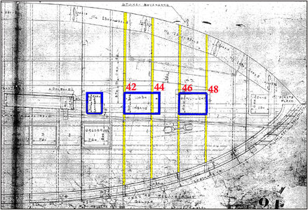
Started with the frame for the lantern. The old drawing shows that it is on a deck plate:
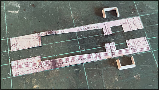
The dimensions are shown: 4900 x 1140 x 6. In scale this becomes 98 x 22.8 x 0.12 mm. That's why I bought the Evergeen 0.13 mm plate.
The frame made of the lantern:
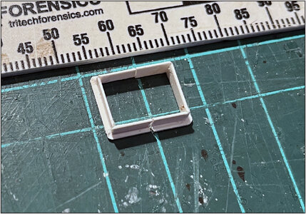
Made divisible into 2 halves. I will make the lantern in its entirety later. This can then be placed over the frame when both halves are against each other. Just like the hatch of the forepeak.
A print made from part of the drawing and cut the plate size out:

Cut out all the recess so that it can serve as a mold.
A test installation around the mast tube and kossing:
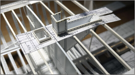
The cover plate should actually also be located under the profile on the side of the mast tube and kossing. That the profile is riveted to the plate. But then I would have had to follow a completely different order of construction. Now I put the plate against it.
After the necessary fitting, measuring and cutting to size, the two plate halves were placed on the deck beams and the 2 frame halves were placed on top of them:
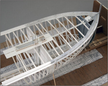
Then cut away the pieces of center profile to the size of the opening.
An extra piece of profile was added lengthwise on both sides of the opening between both deck beams:
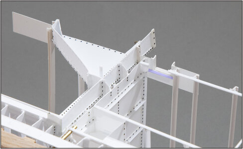
The piece is highlighted in blue for clarity.
This is what the lantern looks like on the Balder from the inside:
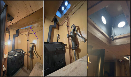
Left: The view to the galley, seen from the forecastle, standing next to the stairs. The arrow points to the lantern.
In the middle: The lantern stands on the deck plate and is otherwise unfinished.
Right: This is in contrast to the light in the forecastle. This has been completed on the current Balder. But the old specifications state that only the deck beams were finished and the metal of the deck plates was looked at. I think I'll stick with the latter.
The now installed deck plate provides extra strength to the construction, especially to the deck beams themselves.
I'm going to adjust my plan slightly and now first install the rest of the deck plates and stringers on the foredeck. That gives extra strength in the areas where the frames for the entrance and lights will be placed and where I also have to remove pieces of the center profile.
Regards, Peter

The dimensions are shown: 4900 x 1140 x 6. In scale this becomes 98 x 22.8 x 0.12 mm. That's why I bought the Evergeen 0.13 mm plate.
The frame made of the lantern:

Made divisible into 2 halves. I will make the lantern in its entirety later. This can then be placed over the frame when both halves are against each other. Just like the hatch of the forepeak.
A print made from part of the drawing and cut the plate size out:

Cut out all the recess so that it can serve as a mold.

A test installation around the mast tube and kossing:

The cover plate should actually also be located under the profile on the side of the mast tube and kossing. That the profile is riveted to the plate. But then I would have had to follow a completely different order of construction. Now I put the plate against it.
After the necessary fitting, measuring and cutting to size, the two plate halves were placed on the deck beams and the 2 frame halves were placed on top of them:

Then cut away the pieces of center profile to the size of the opening.
An extra piece of profile was added lengthwise on both sides of the opening between both deck beams:

The piece is highlighted in blue for clarity.
This is what the lantern looks like on the Balder from the inside:

Left: The view to the galley, seen from the forecastle, standing next to the stairs. The arrow points to the lantern.
In the middle: The lantern stands on the deck plate and is otherwise unfinished.
Right: This is in contrast to the light in the forecastle. This has been completed on the current Balder. But the old specifications state that only the deck beams were finished and the metal of the deck plates was looked at. I think I'll stick with the latter.
The now installed deck plate provides extra strength to the construction, especially to the deck beams themselves.
I'm going to adjust my plan slightly and now first install the rest of the deck plates and stringers on the foredeck. That gives extra strength in the areas where the frames for the entrance and lights will be placed and where I also have to remove pieces of the center profile.
Regards, Peter
Last edited:
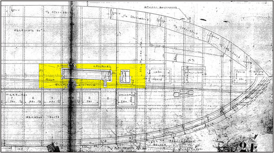
The deck and stringer plates. I had posted this drawing before:

Highlighted are all the plates applied to the deck beams.
This is also clearly visible in this photo of the Vlaardingen restoration at the Bocxe shipyard:
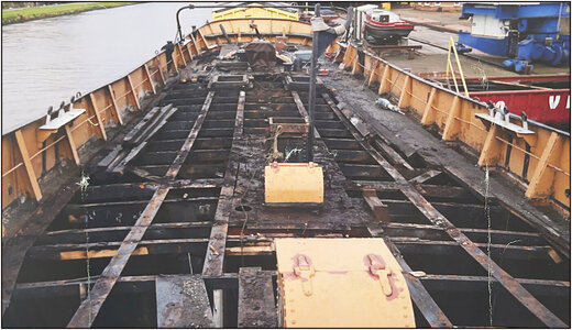
(Source: SZB Restoration Book, page 23)
The photo was taken from front to back. In the foreground the light with just behind it the lantern on the cover plate that also surrounds the mast tube and kossing.
In addition, 2x2 stringer plates run along the length of the ship on which the schaarstokken' will lie. These are the oak beams within which the 'shutters are located. These hatches provide access to the fish holds.
The stringer plates and 2 diagonal plates for the bollards were installed on the foredeck:
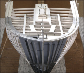
The closing gusset (?) plate was installed on the forepeak on the port side and a profile in which the deck planks would later be enclosed.
The drawing does not indicate how long the stringers are. No idea what lengths they could make back then. The longest of the side stringers is 4.7 meters and the cover plate around the mast tube and kossing is 4.9 meters. I assume a maximum of 6 meters. I then shorten it so that mutual connections are placed around a deck beam. The longest is now 5.5 meters.
From a different position:
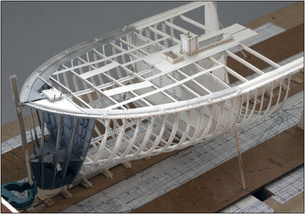
Once all parts have been placed on the deck, apply some heat to straighten a few more deck beams so that the slight unevenness of the stringer is gone.
Then I can now make the frames for the other 4 shutters.
Regards, Peter

Highlighted are all the plates applied to the deck beams.
This is also clearly visible in this photo of the Vlaardingen restoration at the Bocxe shipyard:

(Source: SZB Restoration Book, page 23)
The photo was taken from front to back. In the foreground the light with just behind it the lantern on the cover plate that also surrounds the mast tube and kossing.
In addition, 2x2 stringer plates run along the length of the ship on which the schaarstokken' will lie. These are the oak beams within which the 'shutters are located. These hatches provide access to the fish holds.
The stringer plates and 2 diagonal plates for the bollards were installed on the foredeck:

The closing gusset (?) plate was installed on the forepeak on the port side and a profile in which the deck planks would later be enclosed.
The drawing does not indicate how long the stringers are. No idea what lengths they could make back then. The longest of the side stringers is 4.7 meters and the cover plate around the mast tube and kossing is 4.9 meters. I assume a maximum of 6 meters. I then shorten it so that mutual connections are placed around a deck beam. The longest is now 5.5 meters.
From a different position:

Once all parts have been placed on the deck, apply some heat to straighten a few more deck beams so that the slight unevenness of the stringer is gone.
Then I can now make the frames for the other 4 shutters.
Regards, Peter
Last edited:

